
Prerequisite
It is advisable to first go through Service Creation Platform section at Getting Started guide before proceeding with this hardware tutorial.
Raspberry Pi
Python and MQTT
You need to have:
1. python: most of the time, is installed in the system by default. if you do not have python on your raspberry pi click here for tutorial on how to install it.
To check for python, from the terminal:
$ python If python already installed the terminal will show the details of the version as follow:
pi@raspberrypi:~ $ python
Python 2.7.13 (default, Nov 24 2017, 17:33:09)
[GCC 6.3.0 20170516] on linux2
Type "help", "copyright", "credits" or "license" for more information.
2. paho-mqtt package: this package is necessary to use MQTT protocol to transfer the data to the device on iot.oip.tm.com
To install paho-mqtt package execute the following commandline in the terminal:
$ sudo pip install paho-mqtt3. JSON: necessary to read from JSON files.
In the following script, OIP_HOST is fixed to iot.oip.tm.com . You need to add your access token of the IoT device to ACCESS_TOKEN variable. If you don't know how to get the access token of the IoT device click here for a comprehensive tutorial. For successful connection, you need to have a client to send the data and a receiver to the receive and save the data for later user. In this case, the server is the IoT device on iot.oip.tm.com while the client should be implemented in your code. MQTT protocol will be used to connect with the server. As a result, we need to import paho.mqtt.client library for this purpose and JSON library as a format for the data. First, we define a callback function called on_connect() which will print out the status of the connection to the server. This callback function will be called automatically by the client. Second, we create an instance of the client. After that, we pass the access token to of the IoT device to the client we just created and connect it to the IoT website. We make a loop for the client that will keep sending the data online unless a keyboard interrupt happened. The code of reading the data from the sensor is located inside the client loop.
Sending data via MQTT protocol
#import necessary libraries
import os
import sys
import paho.mqtt.client as mqtt
import json
from time import sleep

#set the needed variables
OIP_HOST = 'iot.oip.tm.com'
ACCESS_TOKEN = '<put-access-token-here>'

# The callback for when the client receives a CONNACK response from the server.
def on_connect(client, userdata, rc, *extra_params):
    print('Connected with result code ' + str(rc))

#Create a client instance
client = mqtt.Client()

#Connect to a broker using one of the connect*() functions
client.on_connect = on_connect
client.username_pw_set(ACCESS_TOKEN)
client.connect(OIP_HOST, 1883, 60)

#keep looping unless interrupted by the user
client.loop_forever()
try:
    while(True):
        #insert your code here to read the data and save it to "sensor_data"
        client.publish('v1/devices/me/telemetry', json.dumps(sensor_data), 1)
        #make some delay to control how frequent to check the status of the sensor
        time.sleep(3)
    except KeyboardInterrupt:
        print('Interrupt!')
        client.loop_stop()
        client.disconnect()
to make the script easy to maintain we read the OIP_host and ACCESS_TOKEN from a JSON file called config.json.
# read data from config file. json only
with open('config.json') as json_data_file:
data = json.load(json_data_file)

OIP_HOST = data['OIP_HOST']
ACCESS_TOKEN = data['ACCESS_TOKEN']
Data format in config.json file
{
    "OIP_HOST": "iot.oip.tm.com.my",
    "ACCESS_TOKEN": "<put-access-token-here>",
    "MQTT_PORT": 1883
}
Ultrasonic Sensor
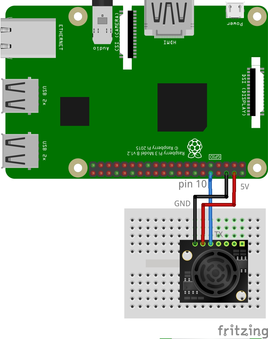
Ultrasonic sensor is a device that can measure the distance to an object using sound waves. It sends out a sound wave at certain frequency and receive its reflection from any object or obstacle. Then by counting the time taken for the wave from the send to the receive and calculate the distance using the following formula: distance = 0.5 x speed of sound x time taken. It is important to understand that some objects might not be detected by ultrasonic sensors. This is because some objects are shaped or positioned in such a way that the sound wave bounces off the object, but are deflected away from the Ultrasonic sensor. It is also possible for the object to be too small to reflect enough of the sound wave back to the sensor to be detected. Other objects can absorb the sound wave all together (cloth, carpeting, etc), which means that there is no way for the sensor to detect them accurately. In this program, an LV-MaxSensor MB1000 is used. This sensor is provided with different types of outputs such as serial output, and analog output that provide the same information (distance from an object). However, we only use serial output to read the distance. Be informed that some of the sensors might need an inverter at the output just like the one used in this program however to confirm whether do you need the inverter on not you need to refer to the datasheet of the sensor you are using. The sensor operates with 5V and can differ in the amount of current it needs to operate. The MB1000 needs 20mA however some other types might need more current where the raspberry pi might not be able to supply hence an external supply is needed. The minimum distance that is detectable by MB1000 is 6 inches and can vary according to the sensor used. In the programing side, to read data from the sensor using the serial protocol we need to import two libraries on top of those mentioned in the [MQTT in Python] section. The first one is time to count the time taken to receive data form the sensor and the second one is 'Serial' to manage the serial communication. The default directory of the serial devices in the raspberry pi is "/dev/ttyAMA0" or "/dev/ttyS0". The data that will be obtained and pushed online is called Distance and is measured in inches.
Requirements
Before starting you need to have:
1. Need to activate the SPI in the Raspberry pi: either activate it from the terminal or by browsing to the raspberry pi configuration in the raspberry pi menu. To do it from the terminal write the following command line in the terminal and from the interface options enable SPI.
To access the raspberry pi configuration from the terminal
$ sudo raspi-config2. To use the serial device you need to deactivate the Bluetooth as they use the same device module (AMA0) and only one of them can work at the time. To do so you need to add the following three lines to the end of /boot/config.txt file:
enable_uart=1
dtoverlay=pi3-disable-bt
dtoverlay=pi3-miniuart-bt
To edit the config.txt file run the following command in the terminal
$ sudo nano /boot/config.txtHow to read from the Sensor
Python script to read data from the sensor
from time import time
from serial import Serial

serialDevice = "/dev/ttyAMA0" # default for RaspberryPi
maxwait = 3 # seconds to try for a good reading before quitting
sensor_data = {'Distance': ' '}

def measure(portName):
    ser = Serial(portName, 9600, 8, 'N', 1, timeout=1)
    timeStart = time()
    valueCount = 0

    while time() < timeStart + maxwait:
        if ser.inWaiting():
            bytesToRead = ser.inWaiting()
            valueCount += 1
            if valueCount < 2: # 1st reading may be partial number; throw it out
                continue
            testData = ser.read(bytesToRead)
            if not testData.startswith(b'R'):
                # data received did not start with R
                continue
            try:
                sensorData = testData.decode('utf-8').lstrip('R')
            except UnicodeDecodeError:
                # data received could not be decoded properly
                continue
            try:
                mm = int(sensorData)
            except ValueError:
                # value is not a number
                continue
            ser.close()
            return(mm)

    ser.close()
    raise RuntimeError("Expected serial data not received")

#the following lines are to be placed in the client loop

measurement = measure(serialDevice)
print "distance =",measurement
sleep(2)
sensor_data['Distance']=str(measurement)+" Inches"
client.publish('v1/devices/me/telemetry', json.dumps(sensor_data), 1)
Schematic Diagram
PIR Sensor
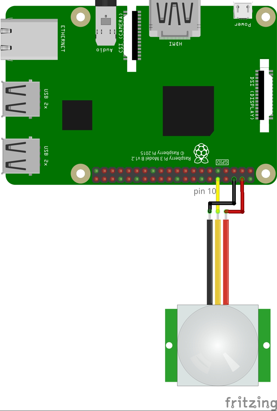
PIR sensor is a motion sensor where it consists of a Fresnel lens, an infrared detector, and supporting detection circuitry. The Fresnel lens is used to focus the infrared radiation from moving bodies to the infrared detector. The sensor will give an output as (high) when there is a motion within its range and (low) if no motion is detected.
How to read from the Sensor
python script to read data from the sensor
import RPi.GPIO as gpio
PIR_Input=10 # output pin of the sensor is connected to pin number 10
gpio.setmode(gpio.BOARD)
gpio.setup(PIR_Input,gpio.IN,pull_up_down=gpio.PUD_DOWN)
if (gpio.input (PIR_Input)==1):
    sensor_data['movement']=True
else:
    sensor_data['movement']=False
In the above code, change the pin number in PIR_Input according to your connections. If you are using an external resistance change the setup of the used pin as follows:
gpio.setup(PIR_Input,gpio.IN)Sensor has three pins labeled as VCC,GND,output. It is connected to 3.3V or 5V (refer to sensor datasheet) and when it detects a motion within its range it will give a high output (3.3V or 5V). We used the built in resistor to pulldown the input. if you are using an external resistance change the setup of the used pin.
Schematic Diagram
LDR Sensor
LDR or Photoresistor sensor is a light variable resistor. The resistance of a phototresistor decreases with increasing incident light intensity. In this program an RC circuit is built to be able to make use of the change of the resistor of the LDR by observing the change in the time needed to charge the capacitance. When there is no light, the time needed to charge the capacitor is large as the time constant will be too high as the resistor is high in the darkness (around 20M ohm). When there is light, the time needed to charge the capacitor is shorter as the time constant will be smaller due to the change in the light intensity. We use the percentage of change the time needed to charge the capacitor as an indicator of the light intensity. We connect one of the sensor's legs to 3.3V or 5V and the other leg will be connected to the positive leg of the capacitor. The negative leg of the capacitor will be connected to the ground. Then we take the readings from the point between the sensor and the capacitor. First, we make sure that the capacitor is empty so we discharge it by making the pin connected to it LOW. you can only set the pin LOW or HIGH only if it is in the output mode hence we set it as an output pin and then set it low to discharge the capacitor. After that, we change it to an input pin and count how long does it take for the capacitor to charge (the pin becomes high logic). For more information on this design click here.
How to read from the Sensor
Python script to read data from the sensor
import RPi.GPIO as gpio
GPIO.setmode(GPIO.BCM)
def RCtime (RCpin):
    reading = 0
    GPIO.setup(RCpin, GPIO.OUT)
    GPIO.output(RCpin, GPIO.LOW)
    sleep(5)
    GPIO.setup(RCpin, GPIO.IN)
     # This takes about 1 millisecond per loop cycle
    while (GPIO.input(RCpin) == GPIO.LOW):
        reading += 1
    return reading

#the following lines are to be placed in the client loop
Reading=RCtime(3)
LDRReading = str (Normalize(Reading) )+' %'
print "Light intensity : ",LDRReading
sensor_data['light intensity']=LDRReading
In the above code, RCtime() take in the pin number that is connected to the sensor
Normalizing the readings
To normalize the readings and to produce percentage values, we choose the highest reading returned by RCtime() which can be obtained in the dark environment as the maximum value. Then, the readings in percentage form can be re-produced using the following equation: light intensity % =(1- current reading / max. reading)* 100.
Normalizing function to produce readings in percentage form
def Normalize(CurrReading):
    CurrReading*=100
    MaxReading=640
    ratio=CurrReading / MaxReading
    NormReading=(100-ratio)
return NormReadingSchematic Diagram

Voice-controlled Smart Light (Mi-Light) via Jasper
Overview
Jasper is an open source platform for developing always-on, voice-controlled applications. The components used in this set-up are:
- 2 units of Raspberry Pi 3 Model B
- 1 unit of USB Microphone
- 1 unit of Typical Earphone Model
- 1 unit of Mi-Light Bridge
In this example, we are going to turn on and off light bulb via voice command and at the same time, the status of the light bulb is updated to the OIP Sevice Creation Platform.
The model of USB microphone is Microsoft LifeCam VX-1000 (only the built-in microphone is used). Any microphone with USB port should work fine with Jasper. Otherwise, a webcam with built-in microphone can also be used as voice input for Jasper.
For the Mi-Light set-up, a Mi-Light bulb and a bulb holder are used.
Mi-Light Set-up
First, attach the Mi-Light to the bulb holder. Mi-Light controller bridge is required. The controller is connected to a Raspberry Pi. Once connected to the Pi, please configure the light by dowloading the app 'Mi-Light Remote' on Play Store. Then, set up the controller by connecting it to your Wifi network via the app you just downloaded. Try to control the light via the app for testing purpose.
After that, identify the IP address assigned to the Mi-Light controller. Then, download Mi-Light files here. Next, open Terminal and then go to the directory of where you saved it .../milight_binaries, open "milight.conf" file and change the IP address to the ASSIGNED IP address by your wifi network. Now, still in the same directory, you can control the light via the Terminal by typing this command "./milight". For example, "./milight on" or "./milight off". Type "./milight" for more information.
Pushing the Light Status to the OIP Service Creation Platform and integrating with RPC Command.
The smart light can be controlled independently and pushing light status without using Jasper. Please download the source code here and run it for testing purposes. When the code is run, it can turn the light on or off, at the same time, it will push the status of the light to the OIP.
In case, you want to obtain credentials and device details, such as Access Token, Device ID, Authorization key, X-authorization key, username, password and etc., You can refer here. These are compulsary parameters.
Configuring the Pi with Jasper
The details and step-by-step installation guides are available here.
The Full Set-up
Two Raspberry Pi are being used. The first Pi is running with Jasper. It will accept the voice command to control the bulb. Meanwhile, the second Pi is running Mi-Light source codes (available here).
The second Pi receives the RPC command triggered by the first Pi (Jasper) via voice. After that, subsequent action will be taken by the second Pi (Mi-Light) based on the voice input.
Additional module to on light
# -*- coding: utf-8-*-
import re
import paho.mqtt.client as mqtt
import requests
import json
WORDS = ["ON"]
PRIORITY = 5

sensor_data = {'light': ' '}

def isValid(text):
    return bool(re.search(r'\b(on)\b', text, re.IGNORECASE))

def handle(text, mic, profile):
    def on_connect(client, userdata, rc, *extra_params):
        print('Connected with result code ' + str(rc))

    url= 'https://api.oip.tm.com.my/app/t/tmrnd.com.my/iot/1.0/api/plugins/rpc/oneway/<Device ID>'
    data_on= '{"method":"setLightStatus","params":{"zone":"1","state":"on","value":""}}'
    headers={"Content-Type": "application/json","X-Authorization":"Bearer <Jason Web Token from OIP Service Creation Platform based on Username/Password>","Authorization":"Bearer <Access Token from OIP Service Exchange Platform>"}

    client = mqtt.Client()
    client.on_connect = on_connect
    client.username_pw_set("<Access Token of Device>")
    client.connect("iot.oip.tm.com.my", 1883, 60)
    client.loop_start()
    try:
        response = requests.post(url, data=data_on,headers=headers)
        sensor_data['light']='ON'
        print(response.status_code)
        print(sensor_data)

        response=client.publish('v1/devices/me/telemetry', json.dumps(sensor_data), 1)
        #make some delay to control how frequent to check the status of the sensor
        print (response)

    except KeyboardInterrupt:
        print('Interrupt!')
        pass

    client.loop_stop()
    client.disconnect()
Additional module to off light
# -*- coding: utf-8-*-
import re
import paho.mqtt.client as mqtt
import requests
import json
WORDS = ["OFF"]
PRIORITY = 6

sensor_data = {'light': ' '}

def isValid(text):
    return bool(re.search(r'\b(off)\b', text, re.IGNORECASE))

def handle(text, mic, profile):
    def on_connect(client, userdata, rc, *extra_params):
        print('Connected with result code ' + str(rc))

    url= 'https://api.oip.tm.com.my/app/t/tmrnd.com.my/iot/1.0/api/plugins/rpc/oneway/<Device ID>'
    data_off= '{"method":"setLightStatus","params":{"zone":"1","state":"off","value":""}}'
    headers={"Content-Type": "application/json","X-Authorization":"Bearer <Jason Web Token from OIP Service Creation Platform based on Username/Password>","Authorization":"Bearer <Access Token from OIP Service Exchange Platform>"}

    client = mqtt.Client()
    client.on_connect = on_connect
    client.username_pw_set("<Access Token of Device>")
    client.connect("iot.oip.tm.com.my", 1883, 60)
    client.loop_start()
    try:
        response = requests.post(url, data=data_off,headers=headers)
        sensor_data['light']='OFF'
        print(response.status_code)
        print(sensor_data)
        response=client.publish('v1/devices/me/telemetry', json.dumps(sensor_data), 1)
        #make some delay to control how frequent to check the status of the sensor
        print (response)

    except KeyboardInterrupt:
        print('Interrupt!')
        pass

    client.loop_stop()
    client.disconnect()
For example, any voice input that contains the word "on" will trigger isValid(text) function and therefore, the module that contains the keyword "on" will be executed. What will be executed by the module is defined in handle(text, mic, profile) function. In this case, the module will make RPC POST request, establish MQTT connection and push the light status to OIP. This function and proccess apply to the "off" module and all other modules which are created by users.
Save the above Python scripts in two seperate python files, the above codes will wait for user input keyword "ON" and "OFF" Next, copy the saved files of above scripts to ~/jasper/client/modules depending on where the Jasper folder is located. For example, /home/pi/. This is done on the first Pi (Jasper).
In case, you want to obtain credentials and device details, such as Access Token, Device ID, Authorization key, X-authorization key, username, password and etc., You can refer here. These are compulsary parameters.
How to Run
Download this to run Mi-Light on 2nd Pi.
python sensor_milight.py
To run Jasper on 1st Pi, go to the folder where you saved Jasper then,
python jasper.py
Example:
You: “Jasper”
Jasper: high beep
You: ON
Jasper: low beep
Jasper: Mi-Light is on and light status pushed
Good luck and have fun interacting with Jasper.
Extras
Jasper comes with pre-build modules which are used by Jasper to perform specific tasks. On the other hand, users also can write their own modules to allow Jasper to perform various tasks that users desire. In this mini project, two additional modules have been added which are used to control Mi-Light via voice commands.
U-Blox C027
Push Data online using MQTT protocol
Pushing data online is the main point in IoT applications where the user pushes the collected data from sensors' network to the cloud or the platform for farther process and analysis. To be able to push the data online, the user needs to connect to the cloud through internet, using protocols such as HTTP(S), COAP, MQTT and etc. This documentation will illustrate how to connect to the internet and send the data to the online platform using MQTT protocol using Mbed based board. The Mbed board used in this tutorial is Ublox C027 click here.
Requirements
You need to have the following below you start:
1. You need to have an access to the online Mbed complier or install Mbed client for offlline usage; For more information, please click here. Note that online compiler will be used in this tutorial.
2. You need to create a new program from the "New" menu at the top left of the online complier. Choose your board in the platform box and you can either choose "hello world" template or choose an empty program template; Name the program and click "OK".
3. Import the following libraries to your program:
* EthernetInterface
* mbed-rtos
* MQTT
* mbed
or you can import "K64F-RTOS-MQTT-Example" program and copy its libraries.
4. Connect your U-Blox C027 board with an Ethernet connection.
Pushing data using MQTT
In the program file you just created, create a new file called "main.cpp" and start writing your program in this file.
To start you need to include the following header files in your program:
#include "mbed.h"
#include "MQTTClient.h"
#include "MQTTEthernet.h"
#include "rtos.h"

//define some important constants as follows:

#define BROKER "iot.oip.tm.com.my"          // MQTT broker URL
#define PORT 1883                           // MQTT broker port number
#define CLIENTID "104421251"                // The name that will appear for the server (can be anything as long as there is no similar id connecting to the platform)
#define USERNAME "add access token here"    //  use the Access Token of the device as a user name
#define TOPIC "v1/devices/me/telemetry"     // the directory of the device in the platform
If you don't know how to get the access token of the IoT device click here for a comprehensive tutorial. You need to have a client to send the data up to OIP Service Creation Platform. Once the platform receives it, the data will be stored at OIP Service Creation Platform. The data then can be retrieved for later user. The OIP Service Creation Platform for the IoT device is located at iot.oip.tm.com. The client should be implemented in your code. MQTT protocol is the transport protocol chosen to connect to the OIP Service Creation Platform. To be able to debug your program for any errors, you need to connect the board to your PC or Laptop and using CoolTerm or any other serial communication softwares that you can view the messages from your board.
Set the serial communication
Serial pc(USBTX,USBRX);
Main Function
In the main function, start by connecting to the Ethernet by making use of the "EthernetInterface" and "MQTTEthernet" libraries. You can print out the IP, MAC, and Gateway addresses. Create an instance of the MQTT client called "client". Initialize the hostname and the port to "BROKER","PORT" respectively. In the data you need to send, you only add the client id and the username while password is not required. Finally, the data that will be sent online should be written in JSON format as {"key":"value"} pairs and then use sprintf(); to convert it to a suitable format. Finally, publish the message and disconnect the client.
main function
int main() {
   pc.printf("\r\nAttempting connect to local network...\r\n");

   // initialize ethernet interface
   MQTTEthernet ipstack = MQTTEthernet();

   // get and display client network info
   EthernetInterface& eth = ipstack.getEth();
   pc.printf("IP address is %s\r\n", eth.getIPAddress());
   pc.printf("MAC address is %s\r\n", eth.getMACAddress());
   pc.printf("Gateway address is %s\r\n", eth.getGateway());

   // construct the MQTT client
   MQTT::Client<MQTTEthernet, Countdown> client = MQTT::Client<MQTTEthernet, Countdown>(ipstack);

   char* hostname = BROKER;
   int port = PORT;
   int rc;                //response code

   pc.printf("\r\nAttempting TCP connect to %s:%d:  ", hostname, port);

   // connect to TCP socket and check return code
   if ((rc = ipstack.connect(hostname, port)) != 0)
      pc.printf("failed: rc= %d\r\n", rc);
   else
      pc.printf("success\r\n");

   MQTTPacket_connectData data = MQTTPacket_connectData_initializer;
   data.MQTTVersion = 3;
   data.clientID.cstring = CLIENTID;
   data.username.cstring = USERNAME;

   // send MQTT connect packet and check return code
   pc.printf("Attempting MQTT connect to %s:%d: ", hostname, port);
   if ((rc = client.connect(data)) != 0)
      pc.printf("failed: rc= %d\r\n", rc);
   else
      pc.printf("success\r\n");

   char* topic = TOPIC;
   MQTT::Message message;
   char buf[100];
   char send_online[]="{\"light\":\"00\"}";

   sprintf(buf, send_online);

   message.qos = MQTT::QOS0;
   message.retained = false;
   message.dup = false;
   message.payload = (void*)buf;
   message.payloadlen = strlen(buf);

   pc.printf("Publishing MQTT message: %.*s\r\n", message.payloadlen, (char*)message.payload);

   rc = client.publish(topic, message);
   client.disconnect();
   return 0;
}
Upload program to C027
When you have finished your coding, you need to compile it. If there is no errors in your compilation, a binary file will be built. Connect your board to your laptop using USB cable and make sure you have connected the Ethernet cable. The board drive will then appear on your computer. Then, copy and paste the binary file to the board drive. A red led will stat blinking on the board, wait until it stops. Open your Coolterm software and connect to the board. Finally, press the reset button on the board to start the execution of your new program.
Temperature Sensor
Introduction
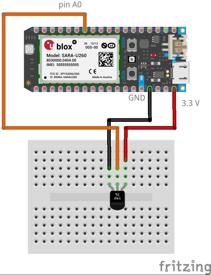
In this tutorial, a MCP9700A analog temperature sensor is used to demonstrate how to read the temperature using the raw data provided by the sensor and how to interpret it into the degree Celsius or Fahrenheit representation using mathematical formulas.
Before you start the main function
Before you start the main function you need to define/initialize which pin is connected to the sensor. As the sensor used in this tutorial is an analog sensor, use the analog pin A0 (or any other analog pin).
define the analog pin A0 as an input
AnalogIn ain(A0); // connect A0 to the output of the sensor
Main Function
In the while loop of the MQTT client, read and interpret the data in to Celsius and/or Fahrenheit representation
read, interpret, and push the temperature data to OIP
#ifdef 3V_SUPPORT
float V = ain.read() * 3.3; // connect Vs(TempSensor) to 3.3V
#else
float V = ain.read() * 5; // connect Vs(TempSensor) to 5V
#fi

float tempC = (V-0.5) * 100; // calculate temperature ˚C
float tempF = (tempC * 9 / 5) + 32.0; // calculate temperature F

pc.printf("tempC value : %5.2f ˚C \r\n", tempC);
pc.printf("tempF value : %5.2f F \r\n", tempF);
sprintf(buf, "{\"Temperature\":\"%0.2f ˚C\"}",tempC); // in this tutorial only celsius representation is pushed online

message.qos = MQTT::QOS0;
message.retained = false;
message.dup = false;
message.payload = (void*)buf;
message.payloadlen = strlen(buf);

pc.printf("Publishing MQTT message: %.*s\r\n", message.payloadlen, (char*)message.payload);

rc = client.publish(topic, message);
client.yield(100);
wait(60);// sample temperature every one minute
Schematic Diagram
Dust Sensor
Introduction
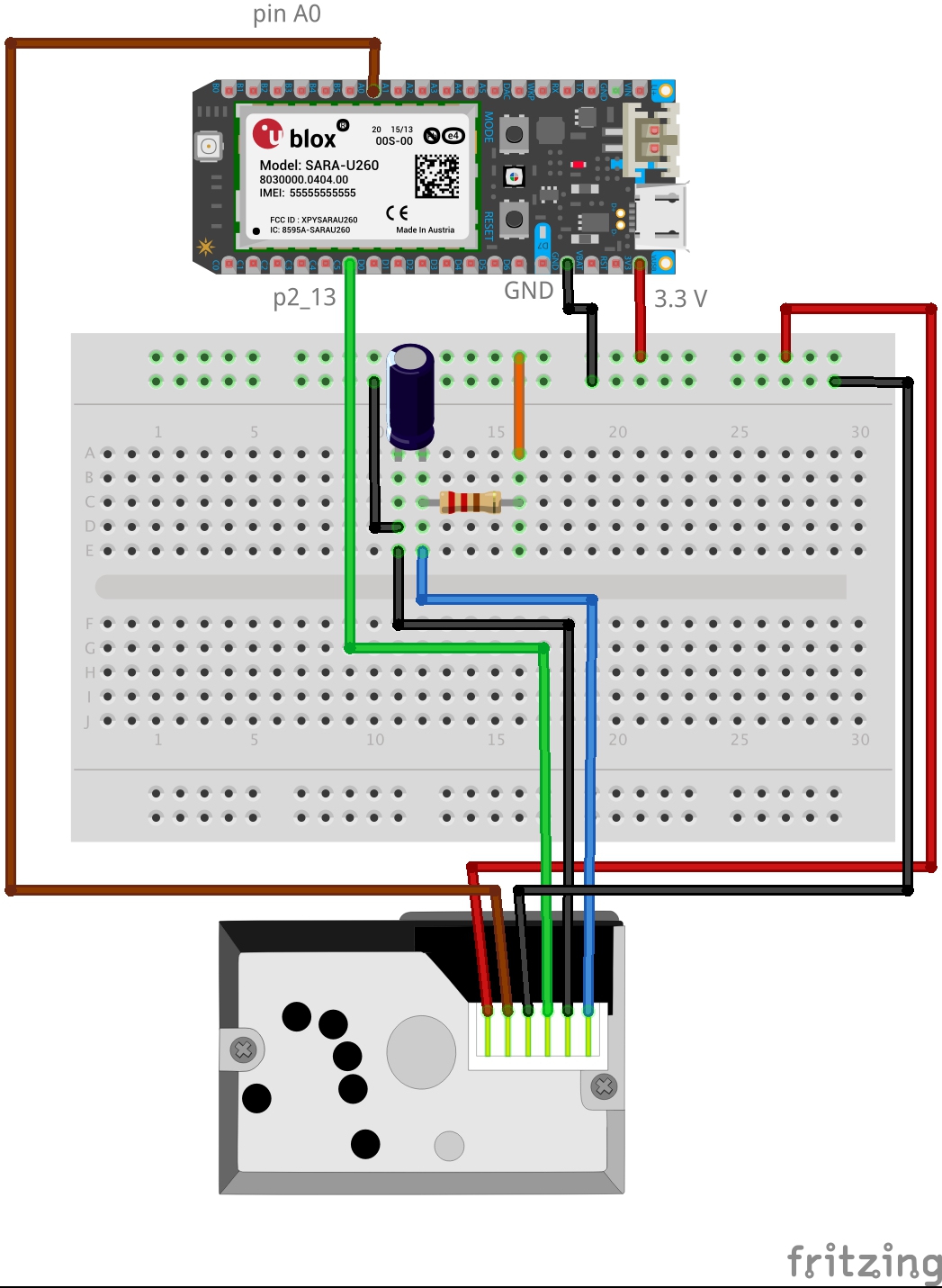
Sharp’s GP2Y1010AU0F is an optical air quality sensor, designed to sense dust particles. An infrared emitting diode and a phototransistor are diagonally arranged into this device, to allow it to detect the reflected light of dust in air. It is especially effective in detecting very fine particles like cigarette smoke, and is commonly used in air purifier systems.
The sensor has a very low current consumption (20mA max, 11mA typical). The output of the sensor is an analog voltage proportional to the measured dust density, with a sensitivity of 0.5V/0.1mg/m3.
In this program, the output voltage is read from the sensor and an equation induced form the discretion and graphs provided in the datasheet of the sensor is used to interpret the data into a meaning full information. It is important to know that after certain range of dust concentration the sensor readings will saturate. There are two different equations provided in this tutorial. The first one is based on the datasheet and the other one was calibrated by Chris Nafis (c) 2012. You can refer to the API "DustSensorDisplay5110" on the mbed platform for the original code.
Read and Push the Dust Sensor Readings to OIP. The following code is integrated with the above MQTT code.
#include "mbed.h"
Serial pc(USBTX, USBRX);         //output for debugging
DigitalOut myled(LED1);
DigitalOut ledPower(P2_13);
AnalogIn analog_value(A0);

int samplingTime = 280;            //280 microseconds
int deltaTime = 40;            //40 us to give total pulse width of 0.32ms
int sleepTime = 9680;            //LED off for 9680 us to take 1 measurement per second

float dustDensityCN = 0,dustDensitySharp = 0, voMeasured=0, voCalc=0;

int main() {
   pc.printf("Starting sensor. It can take a few measurements until it becomes stable.\n");
   myled = !myled;
   ledPower=0;                 // power on the LED. Pull-down to activate

   wait_us(samplingTime);
   voMeasured = analog_value.read();     // Converts and read the analog input value
   wait_us(deltaTime);
   ledPower=1;                 // turn the LED off. Pull up to turn off
   wait_us(sleepTime);

   voCalc = voMeasured*3.3;        //Map 0:1 measured range to 0:3.3V

   dustDensitySharp = 0.5/2.8 * (float(voCalc) - 0.7);
   dustDensityCN = (float(voCalc) - 0.0356)*1.2;    // equation calibrated by Chris Nafis

   pc.printf(" - Measurment value: %1.3f\n", voMeasured);
   pc.printf(" - Voltage calculated: %1.3f\n", voCalc);
   pc.printf(" - Sharp's Dust Density [mg/m3]: %f\n", dustDensitySharp);
   pc.printf(" - C. Nafis' Dust Density [pp.01cf](x10^4): %f\n\n", dustDensityCN,"\n");
   sprintf(buf, "{\"Dust\":\"%1.3f mg/m3\"}",dustDensityCN);// push online ,only, dustDensityCN
Schematic Diagram
GPS Tracker
Introduction
In this tutorial, MQTT protocol is chosen to push the GPS data to OIP rather that MDM module that is built-in on the board (Ublox C027). This is due to the small size of the compiled program that suitable for RAM storage of less than 32KB. A GPS antenna will be used to receive the GPS signal to provide the longitude, latitude, altitude, and speed of the board. The data will be pushed to OIP.
Before you start you need:
1. A SIM card 2. GPS antenna 3. Ublox C027 board with Built-in GPS Sensor
You will need the following mbed libraries
1. mbed.h 2. GPS.h 3. MDM.h
please note that you can find these libraries under a program called "C027_SupportTest"
Important constants needed to use the SIM card
#define SIMPIN      NULL     // PIN code of the SIM card
#define APN         "unet"     // depends on SIM card you are using
#define USERNAME    NULL
#define PASSWORD    NULL
Due to the fact that sending data to the IoT platform too frequently can cause problems to the network connection of Ublox C027 board, a counter was added so that the board will keep receiving the data from the GPS antenna every 10 ms. But the data will only be pushed to OIP at 5 seconds interval. This is to avoid over loading the board or losing connection with the satellite. A "while" loop was introduced with two conditions to check. So that, everytime the board disconnects from the network or an error happens, the connection will be closed and the program will be restarted close the connection.
Connect to OIP using MDM module and update the GPS reading
#include "mbed.h"
#include "GPS.h"
#include "MDM.h"

/*
 * Cellular modem / SIM parameters.
 */
#define SIMPIN      NULL
#define APN         "my3g"     /* "tm4g" "celcom4g" "diginet" */
#define USERNAME    NULL
#define PASSWORD    NULL

int main(void)
{
    /* Create modem object */
    MDMSerial mdm;
    /* Initialize the modem */
    MDMParser::DevStatus devStatus = {};
    MDMParser::NetStatus netStatus = {};
    int ret;
    char buf[512] = "";
    char link[84] = "";
    unsigned int i = 0xFFFFFFFF;
    char http[256] = "";
    char resp[384] = "";
    char mac[6] = "";
    GPSI2C gps;
    const int wait = 10;
    bool abort = false;
    bool mdmOk = mdm.init(SIMPIN, &devStatus);
    int length=0;
    double spead;
    double altitude;
    double la,lo;
    int restart=0;
    int restartCounter=0;

    while(true)
    {
        restart=0;
        while(true)
        {
            mdmOk = mdm.init(SIMPIN, &devStatus);
            mdm.dumpDevStatus(&devStatus);
            printf("mdmOK: %d\n",mdmOk);
            if (mdmOk)
            {
                /* Ensure the modem connection */
                mdmOk = mdm.registerNet(&netStatus);
                mdm.dumpNetStatus(&netStatus);
            }

            /* Create the PDN connection */
            MDMParser::IP ip = mdm.join(APN,USERNAME,PASSWORD);

            if (ip == NOIP)
                printf("Not able to join network");
            else
                mdm.dumpIp(ip);

            /* Retrieve the MAC address as device ID */
            mbed_mac_address(mac);
            printf("MAC address: %02x-%02x-%02x-%02x-%02x-%02x\r\n", mac[0], mac[1], mac[2], mac[3], mac[4], mac[5]);

            if (ip != NOIP)
                break;
        }

        while (!abort)
        {
            while ((ret = gps.getMessage(buf, sizeof(buf))) > 0)
            {
                /* GPS location tracking */
                int len = LENGTH(ret);

                if ((PROTOCOL(ret) == GPSParser::NMEA) && (len > 6))
                {
                    /* talker is $GA=Galileo $GB=Beidou $GL=Glonass $GN=Combined $GP=GPS */
                    if ((buf[0] == '$') || buf[1] == 'G')
                    {
                        #define _CHECK_TALKER(s) ((buf[3] == s[0]) && (buf[4] == s[1]) && (buf[5] == s[2]))
                        if (_CHECK_TALKER("GLL"))
                        {
                            la = 0, lo = 0;
                            char ch;
                            if (gps.getNmeaAngle(1,buf,len,la) && gps.getNmeaAngle(3,buf,len,lo) && gps.getNmeaItem(6,buf,len,ch) && ch == 'A')
                            {
                                printf("\n\n_______________________________");
                                printf("\nGPS Location: %.5f %.5f\r\n", la, lo);
                                printf("_______________________________\n\n");
                            }
                        }
                        else if (_CHECK_TALKER("GGA") || _CHECK_TALKER("GNS") )
                        {
                            altitude = 0;
                            if (gps.getNmeaItem(9,buf,len,altitude)) // altitude msl [m]
                            printf("\n\n_______________________________");
                            printf("\nGPS Altitude: %.1f\r\n", altitude);
                            printf("_______________________________\n\n");
                        }
                        else if (_CHECK_TALKER("VTG"))
                        {
                            spead = 0;
                            if (gps.getNmeaItem(7,buf,len,spead)) // speed [km/h]
                            printf("\n\n_______________________________");
                            printf("\nGPS Speed: %.1f\r\n", spead);
                            printf("_______________________________\n\n");
                        }
                    }
                }
                printf("%d\t",i);// for debugging purpose
                i++;
                // make sure 0,0 cordinates are not pushed online
                if (la==0 || lo==0)
                {
                     i=0;
                     continue;
                }

                // Create socket and send the GPS location to the Application Server
                if (mdmOk && (i== 500/wait))
                {
                    printf("\n");
                    i=0;
                    printf("Make a HTTP Post Request\r\n");
                    int socket = mdm.socketSocket(MDMParser::IPPROTO_TCP);
                    if (socket==-1)
                    {
                        restart=1;
                        break;
                        }
                    printf("socket response is :%d\n",socket);
                    length = sprintf(link, "{\"latitude\":\"%.5f\",\"longitude\":\"%.5f\",\"spead\":\"%.5f\",\"altitude\":\"%.5f\"}",la, lo,spead,altitude);
                    if (socket >= 0)
                    {
                        //mdm.socketSetBlocking(socket, 10000);
                        printf("mdm rc :%d\n", mdm.socketSetBlocking(socket, 10000));
                        int mdmConnect_rc = mdm.socketConnect(socket, " iot.apps.cp.tmrnd.com.my", 80);
                        printf("mdmConnect rc :%d\n",mdmConnect_rc );

                        if (mdmConnect_rc)
                        {
                            printf("%s\r\n", link);
                            sprintf(http, "POST /C027/GPS HTTP/1.1\r\nHost: iot.apps.cp.tmrnd.com.my\r\nContent-Type: application/json\r\nContent-Length: %d\r\n\r\n%s", length, link);
                            printf("%s\r\n", http);
                            mdm.socketSend(socket, http, sizeof(http)-1);
                            ret = mdm.socketRecv(socket, resp, sizeof(resp)-1);
                            printf("ret is %d\n ",ret);
                            if (ret >= 0)
                            printf("Socket Recv \"%*s\"\r\n",ret,resp);
                            mdm.socketClose(socket);
                            // print how many times the disconnection/ reconnection happend
                            printf("\n@@@@@@@@@@@@@@@@@@@@@@@@@@@@@@\nrestart happened %d time\n@@@@@@@@@@@@@@@@@@@@@@@@@@@@@@\n",restartCounter);

                        }
                        mdm.socketFree(socket);
                    }
                }
            }

            if (restart==1) break;
            ::wait_ms(wait);
        }
        restartCounter++;
        gps.powerOff();
        mdm.powerOff();
    }
    return 0;
}
The while loops are used to guarantee the connection of the MDM to the INTERNET and the continuos.
Arduino Uno
Pushing data online to OIP using MQTT protocol
Requirements
1. Arduino Uno board 2. ESP8266 WiFi module 3. Some jumper wires to connect the ESP8266 to the Arduino
Prepare the ESP8266 module
Before you can use the ESP8266 WiFi module as a shield to Arduino you have to flash a new firmware to it that is suitable with this tutorial. Here is the firmware that was tested in this tutorial. You can use any of the ESP8266 flasher that can be found online. The connections of the two devices as shown below:
| ESP8266 | Arduino Uno |
|---|---|
| GND | GND |
| VCC | 3.3 V |
| CH_PD | 3.3 V |
| TX | TX |
| RX | RX |
| Reset | float |
| GPIO0 | GND |
| GPIO2 | float |
Important notes
1. Since Arduino Uno operates at 5V while ESP8266 module operates at 3.3V, it is advisable to use logic-level shifter to operate the ESP8266 safely, especially when it receives 5V Rx signal from Arduino Uno. However, in this tutorial ESP8266 is connected directly to the Arduino Uno without in logic-level shifter and it is still working.
2. To be able to flash the firmware successfully you need to upload an empty sketch to the Arduino Uno. Then, from Tools/Board choose Generic ESP8266 Module, check the "COM" number to be used to flash the firmware.
3. To check firmware version
After flashing the new firmware, open again the Arduino IDE and open the serial terminal. use the following AT commands in sequence to check the version of the firmware:
| NO | AT command | Expected Response |
|---|---|---|
| 1 | AT | ok |
| 2 | AT+UART_DEF=9600,8,1,0,0 | ok (to change the boad rate from 115200 to 9600) |
| 3 | AT+GMR | will show the firmware version |
Send Data
You need to include the following libraries:
1. WiFiEspClient.h 2. WiFiEsp.h 3. WiFiEspUdp.h 4. PubSubClient.h 5. SoftwareSerial.h
If these libraries are not installed yet, you can install them from sketch/include library/manage libraries.
To use the ESP8266 as WiFi shield you need to change the connections as follows:
| ESP8266 | Arduino Uno |
|---|---|
| GND | GND |
| VCC | 3.3 V |
| CH_PD | 3.3 V |
| TX | D2 |
| RX | D3 |
| Reset | float |
| GPIO0 | float |
| GPIO2 | float |
For more details on this method or if you want to learn how to integrate a sensor into this code please click HERE.
Source code to push data to OIP using MQTT protocl
// include necessary libraries
#include <WiFiEspClient.h>
#include <WiFiEsp.h>
#include <WiFiEspUdp.h>
#include <PubSubClient.h>
#include "SoftwareSerial.h"

// define wifi SSID and password, set the access token and the host address (oip platform)
#define WIFI_AP "WIFI_SSID"
#define WIFI_PASSWORD "WIFI_PASSWORD"
#define TOKEN "ACCESS_TOKEN"            // Access Token from the device listed in OIP Service Creation Platform
char OIPServer[] = "iot.oip.tm.com.my";

// Initialize the Ethernet client object
WiFiEspClient espClient;

PubSubClient client(espClient);

SoftwareSerial soft(2, 3); // TX, RX

int status = WL_IDLE_STATUS;
unsigned long lastSend;

void setup() {
   // initialize serial for debugging
   Serial.begin(9600);
   InitWiFi();
   client.setServer( OIPServer, 1883 );
   lastSend = 0;
}

void loop() {
   status = WiFi.status();
   if ( status != WL_CONNECTED) {
      while ( status != WL_CONNECTED) {
         Serial.print("Attempting to connect to WPA SSID: ");
         Serial.println(WIFI_AP);
         // Connect to WPA/WPA2 network
         status = WiFi.begin(WIFI_AP, WIFI_PASSWORD);
         delay(500);
      }
      Serial.println("Connected to AP");
   }

   if ( !client.connected() ) {
      reconnect();
   }

   getAndSendTemperatureData();
   client.loop();
}

void getAndSendTemperatureData()
{
   // data to be sent
   float t = 30.1;

   Serial.print("Temperature: ");
   Serial.print(t);
   Serial.print(" *C ");

   String temperature = String(t);

   // Just debug messages
   Serial.print( "Sending temperature: [" );
   Serial.print( temperature );
   Serial.print( "]   -> " );

   // Prepare a JSON payload string
   String payload = "{";
   payload += "\"temperature\":"; payload += temperature;
   payload += "}";

   // Send payload
   char attributes[100];
   payload.toCharArray( attributes, 100 );
   client.publish( "v1/devices/me/telemetry", attributes );
   Serial.println( attributes );
}

void InitWiFi()
{
   // initialize serial for ESP module
   soft.begin(9600);

   // initialize ESP module
   WiFi.init(&soft);

   // check for the presence of the shield
   if (WiFi.status() == WL_NO_SHIELD) {
      Serial.println("WiFi shield not present");
      // don't continue
      while (true);
   }

   Serial.println("Connecting to AP ...");

   // attempt to connect to WiFi network
   while ( status != WL_CONNECTED) {
      Serial.print("Attempting to connect to WPA SSID: ");
      Serial.println(WIFI_AP);
      // Connect to WPA/WPA2 network
      status = WiFi.begin(WIFI_AP, WIFI_PASSWORD);
      delay(500);
   }

   Serial.println("Connected to AP");
}

void reconnect() {
   // Loop until we're reconnected
   while (!client.connected()) {
      Serial.print("Connecting to OIP ...");
      // Attempt to connect (clientId, username, password)
      if ( client.connect("Arduino Uno Device", TOKEN, NULL) ) {
         Serial.println( "[DONE]" );
      } else {
         Serial.print( "[FAILED] [ rc = " );
         Serial.print( client.state() );
         Serial.println( " : retrying in 5 seconds]" );
         // Wait 5 seconds before retrying
         delay( 5000 );
      }
   }
}
Libelium Waspmote
Water leakage Detector
Introduction
Water Leakage Detection is use to detect the leakage or to stop the overflow. For example leakage in the roof or ceiling and overflow of water in toilet tank can be easily solved using this sensor. Thus in this program, we used three types Waspmote board to detect the leakage and push the data to OIP using HTTPS. The first board will be the Waspmote Pro v1.2 where this is the main hardware board to use with other waspmote board. The next board will be Waspmote Events Sensor Board v2.0 that will be connected or plug into Waspmote Pro v1.2 to detect the sensor and read the value. As we can see in the datasheet, Waspmote Events Sensor Board v2.0 can support up to 10 sensors and we just need to connect the sensor into the board and we can use it. For this program we only applies one sensor which is water leakage sensor. The last board that we used in this program is Waspmote 3g/gprs v1.0 where it is used to send data that received from the sensor to the OIP Service Creation Platform. There are alternative way to send data to OIP Service Creation Platform such as using WiFi module but in this program, we just use 3G module. The 3G module need to be connected with Waspmote Pro v1.2. Thus, the manual for setting up the boards can be referred from datasheet
Requirement
Libelium has its own Integrated Developer Environment (IDE) for waspmote. Waspmote PRO IDE – v06. You can press this link to download the IDE.
Reading from the Sensor
The Waspmote PRO IDE – v06 have its own library for each board and for each sensor.
For Waspmote Event Sensor, use the following library:
#include <WaspSensorEvent_v20.h>
Thus the library can be chosen based on its respective sensor board. The datasheet provides information about the waspmote board for better understanding. The code for the sensor can be get in the Waspmote IDE (File>examples>sensor>event_20) but it will be basic code and need to change according to the type of sensor used and output needed by the user. In this program,the code has been changed according to water detection sensor. Since the sensor was connected to socket 1 and delay needed for the sensor to read the value is one minute, the code have modified based on the requirement.
Full code on reading the sensor.
#include <WaspSensorEvent_v20.h>

// Variable to store the read value
float value;

void setup()
{
  // 1. Initialization of the modules

  // Turn on the USB and print a start message
  USB.ON();
  USB.println(F("start"));

  // Turn on the sensor board
  SensorEventv20.ON();

  // Turn on the RTC
  RTC.ON();

  // Enable interruptions from the board
  SensorEventv20.attachInt();
}

void loop()
{
  value = SensorEventv20.readValue(SENS_SOCKET1);

  // Print the info
  USB.print(F("Sensor output: "));
  USB.print(value);
  USB.println(F(" Volts"));

  USB.println(F("enter deep sleep"));
  PWR.deepSleep("00:00:01:00",RTC_OFFSET,RTC_ALM1_MODE1,SOCKET0_OFF);

  USB.ON();
  USB.println(F("wake up\n"));

  // 3.1. Check interruption from Sensor Board
  if(intFlag & SENS_INT)
  {
    interrupt_function();
  }

  // 3.2. Check interruption from RTC alarm
  if( intFlag & RTC_INT )
  {
    USB.println(F("-----------------------------"));
    USB.println(F("RTC INT captured"));
    USB.println(F("-----------------------------"));

    // clear flag
    intFlag &= ~(RTC_INT);
  }
}

void interrupt_function()
{
  // Disable interruptions from the board
  SensorEventv20.detachInt();

  // Load the interruption flag
  SensorEventv20.loadInt();

  // In case the interruption came from socket 8
  if( SensorEventv20.intFlag & SENS_SOCKET1)
  {
    USB.println(F("-----------------------------"));
    USB.println(F("Interruption from socket 1"));
    USB.println(F("-----------------------------"));
  }

  // Printing and enabling interruptions
  USB.println(F("Liquid level reached\n"));

  // Clean the interruption flag
  intFlag &= ~(SENS_INT);

  // Enable interruptions from the board
  SensorEventv20.attachInt();
}
Output
The sensor will give voltage as the output. The maximum voltage will be 3.3v and the minimum will be 0v. Based on the datasheet of Waspmote Event Board v2.0, if there is water presence or detected on the sensor the value will be more than 0.5v. Thus to make the leakage detection process to be simple, if else function have been added into the code to give the output as 1 or 0. The output 1 indicates that there is a leakage meanwhile 0 indicates that there is no leakage.
if else function to classify the output.
int level

void loop()
{
   if (value<=0.5)
      level=0;
   else
      level=1;
}
Pushing data through HTTPS.
The OIP Service Creation Platform allows the user to push data from a device to the platform via MQTT or HTTPS protocol. This section shows the steps to be taken for data sharing purposes. Waspmote 3g/gprs does not support MQTT, thus data pushing process will be concentrated using HTTPS.
Steps:
1) Login to OIP Service Creation Platform and get the access token for your listed device that the data to be pushed to.
2) In the waspmote IDE, choose the waspmote 3g library.
3) Sample code to get the reading from sensor and push the data to the OIP Service Creation Platform can be obtained from the IDE (file->examples->communication->3g->getting_url). The code will be modified based on the output requirement.
4) It is important to set the APN of the SIM card correctly to access the network.
Since the data is sent in JSON format, thus it is important for the user to send the data in this format "{\"Leakage Detection\":\"%d\"}", where Leakage Detection will be the key and %d will be the values that update in the platform. As this is POST method, it is compulsory to send the content length together and the length is calculated using strlen function. There is differences in using HTTP and HTTPS where the port number need to change from 80 to 443 and the word "readURL" to "readURLS" in the code. Since this program needs to use HTTPS, thus the basic code have been change accordingly.
There will be an error -14 when we using HTTPS which indicate that the 3g buffer cannot store the response from the server. Although there is an error but still the data can be pushed to the server. Thus the problem can be silently ignored.
Waspmote 3g library
#include <Wasp3G.h>
Variable needed to push data.
int8_t answer;
char aux_str[200];
char aux_str2[40];
int level;
Setting up the APN based on the sim card used and connecting it to the network.
void setup()
{
   // 1. sets operator parameters
   _3G.set_APN("webewbiz", "", "");
   // And shows them
   _3G.show_APN();
   USB.println(F("---******************************************************************************---"));
   // 2. activates the 3G module:
   answer = _3G.ON();
   if ((answer == 1) || (answer == -3))
   {
      USB.println(F("3G module ready..."));

      // 4. Waits for connection to the network
      answer = _3G.check(180);
      if (answer == 1)
      {
         USB.println(F("3G module connected to the network..."));
      }
      else
      {
         USB.println(F("3G module cannot connect to the network..."));
      }
   }
   else
   {
      // Problem with the communication with the 3G module
      USB.println(F("3G module not started"));
   }
}
As the server only accept HTTPS,the code should change to
_3G.readURLS("iot.oip.tm.com.my", 443, aux_str);Since we are sending the data to the platform then we need to make a POST request
void loop()
{

  _3G.ON();
  _3G.check(180);

  USB.printf("%d",level);
  USB.print(F("Getting URL with POST method..."));
  int len = sprintf(aux_str2,"{\"Leakage Detection\":\"%d\"}",level);
  USB.printf("%d",len);
  sprintf(aux_str, "POST /api/v1/QKcimaXJvYARI6dhuWn8/telemetry HTTP/1.1\r\nHost:iot.oip.tm.com.my\r\ncontent-type: application/json\r\nContent-Length: %d\r\n\r\n%s",len,aux_str2 );
  USB.printf(("[%s]\n",aux_str2));

  answer = _3G.readURLS("iot.oip.tm.com.my", 443, aux_str);

  // Checks the answer
  if ( answer == 1) //|| answer==-14)
  {
     USB.println(F("Done"));
     USB.println(_3G.buffer_3G);
  }
  else if (answer < -14)
  {
     USB.print(F("Failed. Error code: "));
     USB.println(answer, DEC);
     USB.print(F("CME error code: "));
     USB.println(_3G.CME_CMS_code, DEC);
  }
  else
  {
     USB.print(F("Failed. Error code: "));
     USB.println(answer, DEC);
  }

_3G.OFF();
Freedom Development Platform (K64F)
Bricking and Unbricking
First and foremost, it is important to highlight a problem that you may encounter if you are using Windows. Most of the Windows users are likely to encounter a situation where the bin file cannot be uploaded to the board. The board itself will automatically remove the bin file as soon as you upload it. Another big problem is when you enter the BOOTLOADER mode (holding the reset button and plugging in the micro usb to the openSDA slot simultaneously), the device will stuck in the BOOTLOADER mode even after you restart the device. The major reason behind these problems is that the OpenSDA application gets confused by files written by the Windows machine to the device. Thus it will erase the openSDA application and the board cannot be debugged with openSDA anymore. Luckily there are several steps that you can follow to overcome these problems.
Steps:
1. Get your device into the BOOTLOADER mode by holding the reset button while plugging the micro-usb. You can see in your computer that the device's name changed to BOOTLOADER.
2. Next, you need to install the Group Policy Editor. You can dowload by clicking GPEdit.msc
3. Click Window+R on your keyboards and the Run command will pops up. Write gpedit.msc and click Ok. This brings you to the Local Group Policy editor.
4. Go to Computer Configuration. Then click on the Administrative Templates folder -> Windows Components -> Search.
5. Search for a setting named "Do not allow locations on removable drives to be added to libraries" and enabled it.
6. Now you need to install debug application. Make sure that your device is in the bootloader mode. There are 3 options to choose from which are nxp,pemicro, and J-Link OpenSDA - Generic Firmwares. I suggest the later.
7. After you have downloaded the OpenSDA file, you can directly copy the .SDA file to the BOOTLOADER device. Unplug the device and then plug it back again. This should solve the problem.
Pushing data through MQTT and HTTPS.
The OIP allows the user to push data from a device to the platform via MQTT or HTTPS protocol. This section shows the steps to be taken for data sharing purposes.
MQTT
Steps:
1. You need to have an access to the online Mbed compiler or you can install the Mbed client for offline usage. This tutorial focuses on the online compiler.
2. At the Mbed compiler interface, create a new program. At the top right corner, there is an icon which allow you to choose the type of board you are working on. Choose FDRM K64F. As soon as you click on the device, it pops up an option where you can choose what kind of template you want to use.You can also choose the the empty program template. Name the program and click "OK".
3. Import these libraries to your Program Workspace (click the import icon located at the top left -> Libraries):
* EthernetInterface
* mbed-rtos
* MQTT
* mbed
4. Another option is to import the "HelloMQTT" program and copy its libraries.
5. Connect your FDRM K64F to the internet via ethernet.
6. In the program you just created, create a new file called "main.cpp".
To start you need to define some parameters and include some header files:
#define MQTTCLIENT_QOS2 0
// logMessage is useful to know the current status of the program. you can use any serial application such as coolterm to see the updates.
#define logMessage printf
#include "easy-connect.h"
#include "MQTTNetwork.h"
#include "MQTTmbed.h"
#include "MQTTClient.h"
messageArrived is useful to analyze the data being sent:
int arrivedcount = 0;

void messageArrived(MQTT::MessageData& md)
{
    MQTT::Message &message = md.message;
    logMessage("Message arrived: qos %d, retained %d, dup %d, packetid %d\r\n", message.qos, message.retained, message.dup, message.id);
    logMessage("Payload %.*s\r\n", message.payloadlen, (char*)message.payload);
    ++arrivedcount;
}
Then you need to write the main fuction as following:
int main()
{
    float version = 0.6;
    char* topic = "v1/devices/me/telemetry"; //specify the endpoint of the destination

    logMessage("HelloMQTT: version is %.2f\r\n", version);

    NetworkInterface* network = easy_connect(true);
    if (!network) {
        return -1;
    }

    MQTTNetwork mqttNetwork(network);

    MQTT::Client<MQTTNetwork, Countdown> client(mqttNetwork);

    const char* hostname = "iot.oip.tm.com.my"; //specify the base url
    int port = 1883;
    logMessage("Connecting to %s:%d\r\n", hostname, port);
    int rc = mqttNetwork.connect(hostname, port);
    if (rc != 0)
        logMessage("rc from TCP connect is %d\r\n", rc);

    MQTTPacket_connectData data = MQTTPacket_connectData_initializer;
    data.MQTTVersion = 3;
    data.clientID.cstring = "mbed-sample";
    data.username.cstring = "INSERT THE ACCESS TOKEN HERE";

    if ((rc = client.connect(data)) != 0)
        logMessage("rc from MQTT connect is %d\r\n", rc);

    if ((rc = client.subscribe(topic, MQTT::QOS2, messageArrived)) != 0)
        logMessage("rc from MQTT subscribe is %d\r\n", rc);

    MQTT::Message message;

    // QoS 0
    char buf[100];
    sprintf(buf, "{\"Hello\":\"TM\"}"); //WRITE YOUR DATA HERE IN JSON FORMAT.
    message.qos = MQTT::QOS0;
    message.retained = false;
    message.dup = false;
    message.payload = (void*)buf;
    message.payloadlen = strlen(buf);
    rc = client.publish(topic, message);
    while (arrivedcount < 1)
        client.yield(100);

    if ((rc = client.unsubscribe(topic)) != 0)
        logMessage("rc from unsubscribe was %d\r\n", rc);

    if ((rc = client.disconnect()) != 0)
        logMessage("rc from disconnect was %d\r\n", rc);

    mqttNetwork.disconnect();

    logMessage("Version %.2f: finish %d msgs\r\n", version, arrivedcount);

    return 0;
}HTTPS
Steps:
1. You need to have an access to the online Mbed compiler or you can install the Mbed client for offline usage. This tutorial focuses on the online compiler.
2. At the Mbed compiler interface, create a new program. At the top right corner, there is an icon which allow you to choose the type of board you are working on. Choose FDRM K64F. As soon as you click on the device, it pops up an option where you can choose what kind of template you want to use. You can also choose the the empty program template. Name the program and click "OK".
3. Import the program named "http-example" to your Program Workspace (click the import icon located at the top left -> Program):
4. Connect your FDRM K64F to the internet via ethernet.
5. In the program open the "main-https.cpp" file.
Include the header files as following:
#include "select-demo.h"
#if DEMO == DEMO_HTTPS
#include "mbed.h"
#include "easy-connect.h"
#include "https_request.h"
Since we are sending the data to the platform then we need to make a POST request.
    // POST method to iot.oip.tm.com.my
    {
        printf("\n----- HTTPS POST request -----\n");

        HttpsRequest* post_req = new HttpsRequest(network, SSL_CA_PEM, HTTP_POST, "https://iot.oip.tm.com.my/api/v1/<Access Token of Device>/telemetry"); // verify the URL endpoint.

        post_req->set_debug(true);
        post_req->set_header("Content-Type", "application/json");

        const char body[] = "{\"hellotm\":\"world\"}"; //attached the data to be sent here

        HttpResponse* post_res = post_req->send(body, strlen(body));
        if (!post_res) {
            printf("HttpRequest failed (error code %d)\n", post_req->get_error());
            return 1;
        }

        printf("\n----- HTTPS POST response -----\n");
        dump_response(post_res);

        delete post_req;
    }

    wait(osWaitForever);
}

#endif
Built in sensor: FXOS8700Q
FXOS8700CQ is a built-in sensor available in the board itself. It is composed of two sensors which are the 3-axis linear accelerometer and 3-axis magnetometer. FXOS8700CQ has dynamically selectable acceleration full-scale ranges of ±2 g/±4 g/±8 g and a fixed magnetic measurement range of ±1200 μT. Output data rates (ODR) from 1.563 Hz to 800 Hz are selectable by the user for each sensor. Interleaved magnetic and acceleration data is available at ODR rates of up to 400 Hz. FXOS8700CQ is available in a plastic QFN package and it is guaranteed to operate over the extended temperature range of –40 °C to +85 °C.
Embedded programmable acceleration event functions:
- Freefall and motion detection
- Transient detection
- Vector-magnitude change detection
- Pulse and tap detection (single and double)
- Orientation detection (portrait/landscape)
Embedded programmable magnetic event functions
- Threshold detection
- Vector-magnitude change detection
- Autonomous magnetic min/max detection
- Autonomous hard-iron calibration
Steps to retrieve basic data from the sensor:
1. Create a new program.
2. Import libraries named FXOS8700Q and mbed to your Program Workspace (click the import icon located at the top left -> Library):
3. Create a cpp file within the program. ex: main.cpp
Simple program to retrieve data from the accelerometer and magnetometer:
#include "mbed.h"
#include "FXOS8700CQ.h"
#define DATA_RECORD_TIME_MS 1000

Serial pc(USBTX, USBRX);

// Pin names for FRDM-K64F
FXOS8700CQ fxos(PTE25, PTE24, FXOS8700CQ_SLAVE_ADDR1);     // SDA, SCL, (addr << 1)
Timer t;                         // Microsecond timer, 32 bit int, maximum count of ~30 minutes
// Storage for the data from the sensor
SRAWDATA accel_data;
SRAWDATA magn_data;

void print_reading()
{
    pc.printf("A X:%5d,Y:%5d,Z:%5d   M X:%5d,Y:%5d,Z:%5d\r\n",
              accel_data.x, accel_data.y, accel_data.z,
              magn_data.x, magn_data.y, magn_data.z);
}

int main(void)
{
    // Setup
    t.reset();
    pc.baud(115200);                     // Print quickly! 200Hz x line of output data!
    // Diagnostic printing of the FXOS WHOAMI register value
    printf("\r\n\nFXOS8700Q Who Am I= %X\r\n", fxos.get_whoami());
    fxos.enable();
    fxos.get_data(&accel_data, &magn_data);
    print_reading();

}
Below is the sample code if you want to push the data using MQTT. You can also use HTTPS by integrating the 2 codes that have been provided in previous example:
#define logMessage printf
#define MQTTCLIENT_QOS2 0
#include "easy-connect.h"
#include "MQTTNetwork.h"
#include "MQTTmbed.h"
#include "MQTTClient.h"
#include "FXOS8700CQ.h"
#include "mbed.h"
#define DATA_RECORD_TIME_MS 1000

Serial pc(USBTX, USBRX);
// Pin names for FRDM-K64F
FXOS8700CQ fxos(PTE25, PTE24, FXOS8700CQ_SLAVE_ADDR1);     // SDA, SCL, (addr << 1)
Timer t;                         // Microsecond timer, 32 bit int, maximum count of ~30 minutes
// Storage for the data from the sensor
SRAWDATA accel_data;
SRAWDATA magn_data;

void print_reading()
{
    pc.printf("X:%5d,Y:%5d,Z:%5d   M X:%5d,Y:%5d,Z:%5d\r\n",

              accel_data.x, accel_data.y, accel_data.z,
              magn_data.x, magn_data.y, magn_data.z);
}

int arrivedcount = 0;

void messageArrived(MQTT::MessageData& md)
{
    MQTT::Message &message = md.message;
    logMessage("Message arrived: qos %d, retained %d, dup %d, packetid %d\r\n", message.qos, message.retained, message.dup, message.id);
    logMessage("Payload %.*s\r\n", message.payloadlen, (char*)message.payload);
    ++arrivedcount;
}

int main()
{
    float version = 0.6;
    char* topic = "v1/devices/me/telemetry";

    logMessage("HelloMQTT: version is %.2f\r\n", version);

    NetworkInterface* network = easy_connect(true);
    if (!network) {
        return -1;
    }

    MQTTNetwork mqttNetwork(network);

    MQTT::Client<MQTTNetwork, Countdown> client(mqttNetwork);

    const char* hostname = "iot.oip.tm.com.my";
    int port = 1883;
    logMessage("Connecting to %s:%d\r\n", hostname, port);
    int rc = mqttNetwork.connect(hostname, port);
    if (rc != 0)
        logMessage("rc from TCP connect is %d\r\n", rc);

    MQTTPacket_connectData data = MQTTPacket_connectData_initializer;
    data.MQTTVersion = 3;
    data.clientID.cstring = "mbed-sample";
    data.username.cstring = "<Access Token of Device>";
    if ((rc = client.connect(data)) != 0)
        logMessage("rc from MQTT connect is %d\r\n", rc);

    if ((rc = client.subscribe(topic, MQTT::QOS2, messageArrived)) != 0)
        logMessage("rc from MQTT subscribe is %d\r\n", rc);

    MQTT::Message message;
    MQTT::Message message1;

    char buf[100];             //create a storage for the data to be sent to the platform
    char buf1[100];
    while (true) {
        t.reset();
        pc.baud(115200);         // Print quickly! 200Hz x line of output data!
        // Diagnostic printing of the FXOS WHOAMI register value
        printf("\r\n\nFXOS8700Q Who Am I= %X\r\n", fxos.get_whoami());
        fxos.enable();
        fxos.get_data(&accel_data, &magn_data);
        print_reading();
        sprintf(buf, "{\"acc_x\":\"%5d\", \"acc_y\":\"%5d\", \"acc_z\":\"%5d\"}", accel_data.x, accel_data.y, accel_data.z);
        sprintf(buf1, "{\"mag_x\":\"%5d\", \"mag_y\":\"%5d\", \"mag_z\":\"%5d\"}", magn_data.x, magn_data.y, magn_data.z);
        message.qos = MQTT::QOS0;
        message.retained = false;
        message.dup = false;
        message.payload = (void*)buf;
        message.payloadlen = strlen(buf);

        message1.qos = MQTT::QOS0;
        message1.retained = false;
        message1.dup = false;
        message1.payload = (void*)buf1;
        message1.payloadlen = strlen(buf1);

        rc = client.publish(topic, message);
        rc = client.publish(topic, message1);
        client.yield(100);

        logMessage("Version %.2f: finish %d msgs\r\n", version, arrivedcount);
        wait(5.0f);
    }
    return 0;
}
Upload program to FRDM K64F.
Compile the program and if there is no error a .bin file will be downloaded. Copy the .bin file to the board and press the reset button.
NodeMCU ESP8266
Set up
This board is a very good IoT platform as it has a buit-in WiFi module and its firmware can be customized to support various transport protocols, such as MQTT. To start with this board, you need to first customize the firmware to support MQTT protocol. To do so, please follow the following steps:
1. Visit NodeMCU build website to customize your firmware.
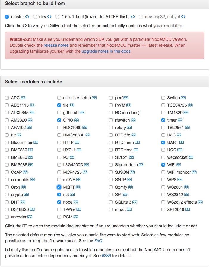
2. After getting the binary file you need to flash it to nodeMCU. To do so, you can use any flasher that can be find online. In this tutorial, nodeMCU flasher master is used.
3. After flashing the firmware to NodeMCU, you can use any IDE such as Arduio IDE or Esplorer to compile your sketch and upload itto ESP8266.
Push Data online using MQTT
We can use mqtt_esp8266 example provided by Adafruit MQTT Library with some modification as follows:
#include <ESP8266WiFi.h>
#include "Adafruit_MQTT.h"
#include "Adafruit_MQTT_Client.h"

#define WLAN_SSID       "SSID"             //wifi network name
#define WLAN_PASS       "PASSWORD"         // wifi network password

#define AIO_SERVER      "iot.oip.tm.com.my"
#define AIO_SERVERPORT  1883                       // use 8883 for SSL
#define AIO_KEY         "ACCESS_TOKEN"         // add you access token here

WiFiClient client;

// Setup the MQTT client class by passing in the WiFi client and MQTT server and login details.
Adafruit_MQTT_Client mqtt(&client, AIO_SERVER, AIO_SERVERPORT, AIO_KEY);

// Setup a feed called 'photocell' for publishing.
Adafruit_MQTT_Publish photocell = Adafruit_MQTT_Publish(&mqtt,"v1/devices/me/telemetry");

void MQTT_connect();

void setup() {
  Serial.begin(115200);
  delay(10);

  Serial.println(F("Adafruit MQTT demo"));

  // Connect to WiFi access point.
  Serial.println(); Serial.println();
  Serial.print("Connecting to ");
  Serial.println(WLAN_SSID);

  WiFi.begin(WLAN_SSID, WLAN_PASS);
  while (WiFi.status() != WL_CONNECTED) {
    delay(500);
    Serial.print(".");
  }
  Serial.println();

  Serial.println("WiFi connected");
  Serial.println("IP address: "); Serial.println(WiFi.localIP());

}

void loop() {

  MQTT_connect();

  // data to be pushed online
  float temp=10.11;

  // make the data to be sent online (payload) in JSON format i.e. {"KEY":"VALUE"}
  String payload = "{";
  payload += "\"temperature\":"; payload += temp;
  payload += "}";

  // Send payload
  char attributes[100];
  payload.toCharArray( attributes, 100 );

  // Now we can publish stuff!
  Serial.print(F("\nSending temperature val "));
  Serial.print(temp);
  Serial.print("...");
  if (! photocell.publish(attributes)) {
    Serial.println(F("Failed"));
  } else {
    Serial.println(F("OK!"));
  }

  delay(1000);
}

void MQTT_connect() {
  int8_t ret;

  // Stop if already connected.
  if (mqtt.connected()) {
    return;
  }

  Serial.print("Connecting to MQTT... ");

  uint8_t retries = 3;
  while ((ret = mqtt.connect()) != 0) {     // connect will return 0 for connected
       Serial.println(mqtt.connectErrorString(ret));
       Serial.println("Retrying MQTT connection in 5 seconds...");
       mqtt.disconnect();
       delay(5000);                // wait 5 seconds
       retries--;
       if (retries == 0) {
         // basically die and wait for WDT to reset me
         while (1);
       }
  }
  Serial.println("MQTT Connected!");
}
RuuviTag Beacon
RuuviTag beacon is a Bluetooth Low Energy (BLE) device. RuuviTag gives a platform for handheld devices to create an interactive connection with the BLE device. There are two firmwares that can be uploaded on to the RuuviTag. Each of the firmware serves different purposes. The Ruuvi firmware is the default firmware installed in the beacon but it is recommended that you upgrade to the latest version. This firmware returns the weather forecast of the area surrounding the beacon. The other available firmware is the Eddystone. This firmware is capable of making the beacon as a proximity beacon. These firmwares can be downloaded here
Here are the steps to flash the firmware to the Ruuvitag:
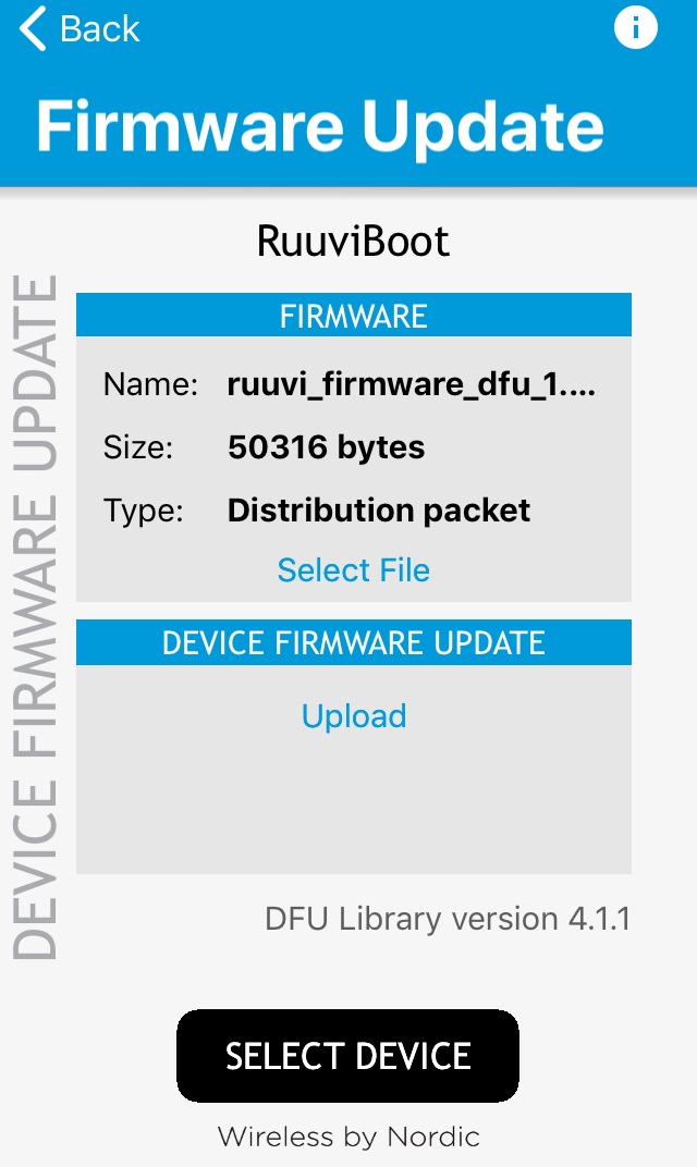
1. Go to this website and download the respective firmware's zip file on your phone.
2. Download the nRF toolbox app. Share the zip file to the respective apps.

3. Hold the B button on RuuviTag and then press the R button once. You will see the red LED lights up.
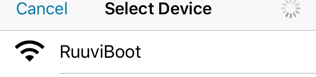
4. On the app, click on the select device tab. Search for the RuuviBoot and click it.
5. Click upload.
Retrieving weather forecast data from RuuviTag
To retrieve the data we need to make use of the RuuviTag sensor Python package. These are the requirements:
1. A RaspberryPi3 as Bluetooth and Internet connection gateway. This is because RuuviTags do not have internet connectivity by themselves.
2. RuuviTag running the Ruuvi firmware.
3. Python 3. Do install the psutil package and Bluez package.
sudo apt-get install python3-dev python3-psutil
sudo apt-get install bluez bluez-hcidump
Raspberry Pi setup
1. Open the terminal.
pip install ruuvitag_sensor2. Update the system.
sudo apt-get update && sudo apt-get dist-upgrade && echo +++ upgrade successful +++3. Run this command and verify that hci0 is in the Blueetoth list. If not, try to reboot the device.
hcitool devInstallation of Ruuvitag_sensor package
1. Firstly, we need to install bluez and bluez-hcidump. Bluez allows a Raspberry Pi to communicate with Bluetooth classic and Bluetooth Low Energy (LE) devices and is included with Raspbian.
sudo apt-get install bluez-hcidump && echo +++ install successful +++2. Upgrade setuptools
sudo pip3 install --upgrade setuptools3. Install Ruuvitag sensor package
pip3 install --user ruuvitag-sensor4. Run this code to get the general usage guide
alias ruuvitag='python3 ~/.local/lib/python3.4/site-packages/ruuvitag_sensor'the output should be:
usage: ruuvitag_sensor [-h] [-g MAC_ADDRESS] [-f] [-l] [-s] [--version]

optional arguments:
  -h, --help            show this help message and exit
  -g MAC_ADDRESS, --get MAC_ADDRESS
                        Get data
  -f, --find            Find broadcasting RuuviTags
  -l, --latest          Get latest data for found RuuviTags
  -s, --stream          Stream broadcasts from all RuuviTags
  --version             show program's version number and exit
5. Insert this command to retrieve data of the nearest RuuviTag.
ruuvitag -fYou should expect to see the MAC address as well as the weather forecast data:
F2:C0:C6:43:AD:03
{'pressure': 1003.0, 'identifier': 'N', 'temperature': 20.0, 'humidity': 52.0}
Sending data to the OIP via MQTT
1. You need a python script to do this. Create a new script and save it at /home/pi/.local/lib/python3.6/site-packages.
2. Below is the sample of the script:
To start you need to include the library:
from ruuvitag_sensor.ruuvitag import RuuviTag
import paho.mqtt.client as mqtt
import json
This snippet will return the weather forecast data
sensor = RuuviTag('DD:A8:8A:B0:91:D3')
state = sensor.update()
state = sensor.state
print(state)
This snippet will push the data to the OIP via MQTT
def on_connect(client, userdata, rc, *extra_params):
    print('Connected with result code ' + str(rc))
client = mqtt.Client()
client.on_connect = on_connect
client.username_pw_set("1jXbYrGLx0kWOqTiovOF") #Access token from OIP website
client.connect("iot.oip.tm.com.my", 1883, 60)
client.loop_start()
response=client.publish('v1/devices/me/telemetry', json.dumps(state), 1)
client.loop_stop()
client.disconnect()
Smart Button
Device Connection
Before you begin receiving data from your IoT devices, you must connect them to OIP Service Creation Platform. A device connection to OIP Service Creation Platform requires device registration with the platform and then using the registration information to configure the device to connect to the platform.
IoT Device Requirements
Before you start connection process, firstly your devices should meet the following requirements for communicating with IoT platform:
-
Your device must be able to communicate using either HTTP or MQTT protocols.
-
The device message must conform to the Service Creation Platform message payload requirements
Login to OIP Service Creation Platform
-
Using the Google Chrome Version 71 and above browser, enter the web address for OIP IoT web portal and the main page will be displayed.
-
The Uniform Resource Locator (URL) for OIP IoT web portal is https://iot.oip.tm.com.my/login
-
Sign up and click submit button for first time user.

- Once sign up has been performed, proceed to sign in.

- The menus are displayed at both left-hand side and centre of the main page.

Logout from OIP Service Creation Platform
-
At the top right, look at the More
-
Click at it and system would automatically log out.
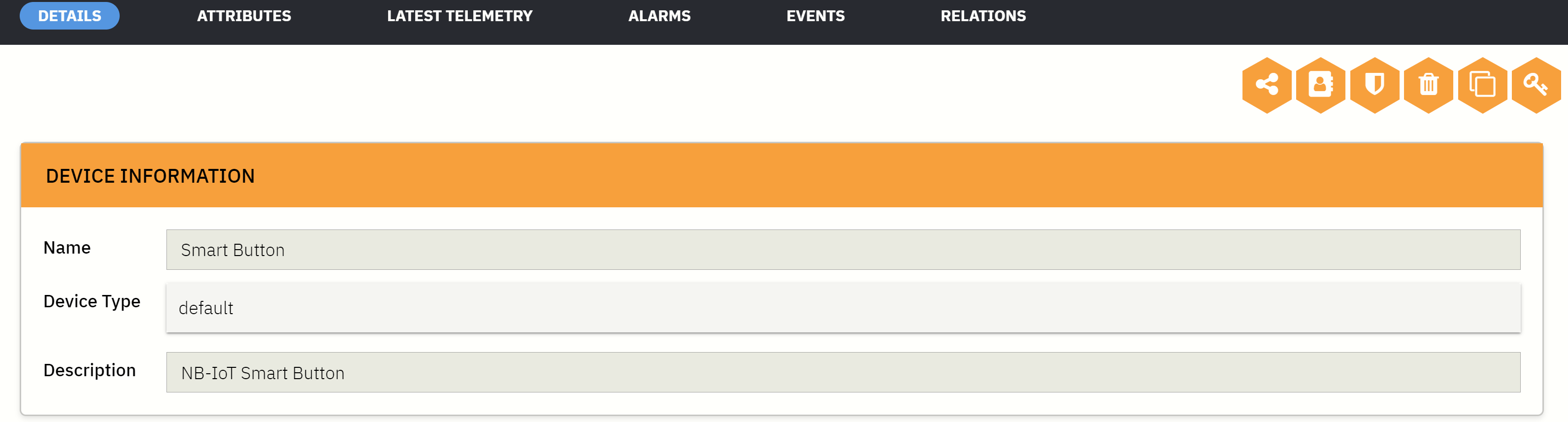
Registration of Device
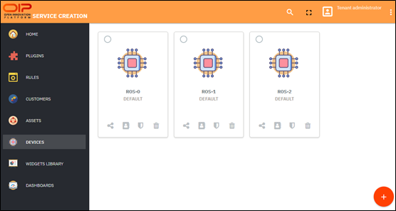
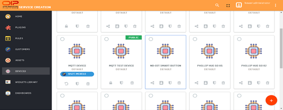
- From the menu pane, select DEVICES or DEVICE MANAGEMENT at the central page and a browser would opened.

- To add a new device, click the plus sign button at bottom right side of the screen.
-
Name the device that you are going to add.
-
Each device that is connected to the platform must be associated with a Device Type. Device types are groups of devices that share common characteristics.
-
Write a brief description on the device at the Description column given.
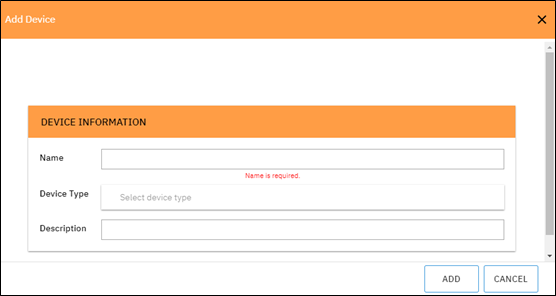
-
Click ADD button to begin the process of adding your device with the selected device type.
-
Click on the device that you have add in and copy its access token.
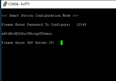
Device Configuration
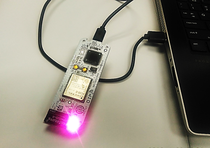
-
Open smart button casing and slot in two AAA batteries.
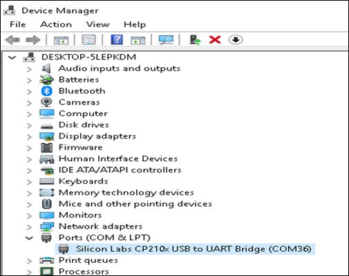
-
Connect the device USB cable and find its virtual COM port.
-
Open serial terminal such as Putty and set up serial connection to the device.
-
Press the device’s button for over 5 second until Smart Button Configuration Mode appears.
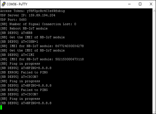
- Enter the password to configure, access token, UDP Server IP and UDP port as prompted.
-
Upon successful configuration, the device will transmit access token once before going to sleep to save power. Validate access token, UDP Server IP and UDP port.
-
Repeat the process if the informations are not correct.
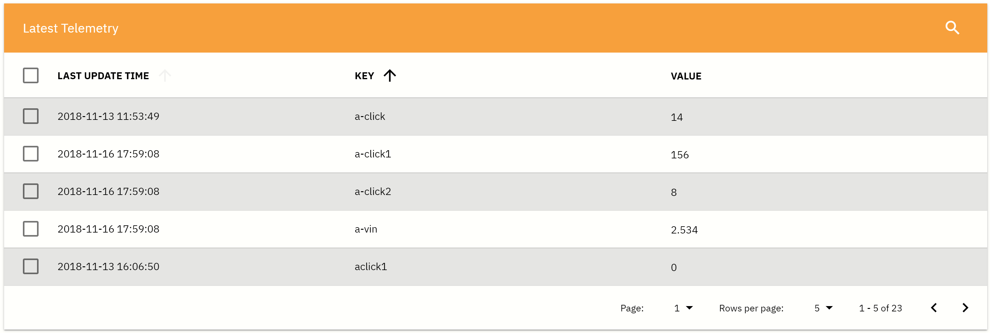
Connection to Service Creation Platform
-
Click on the device recently added.
-
A list of access button can be accessed namely DETAILS, ATTRIBUTES, LATEST TELEMETRY, ALARMS, EVENTS and RELATIONS.
- Click LATEST TELEMETRY to view a list of key-value data being sent earlier.
Configuring Rules
Add New Rule
After you have successfully activated your device and sent some data, it is time to make that data work for you by using rules.
- Click the plus sign at bottom right.
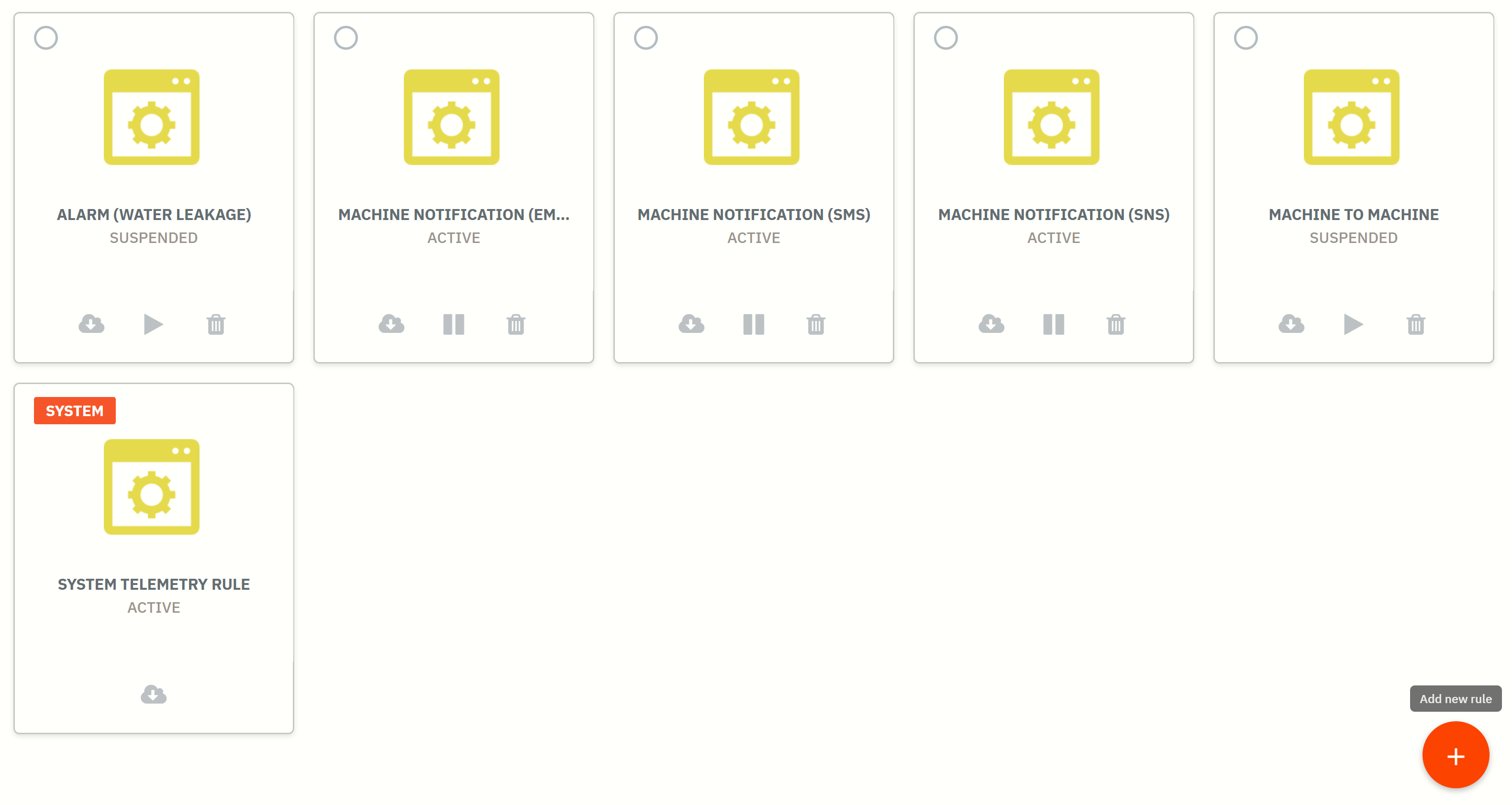
-
Place cursor at the middle and click to create new rule.
-
Place cursor at the top and click to import rule.
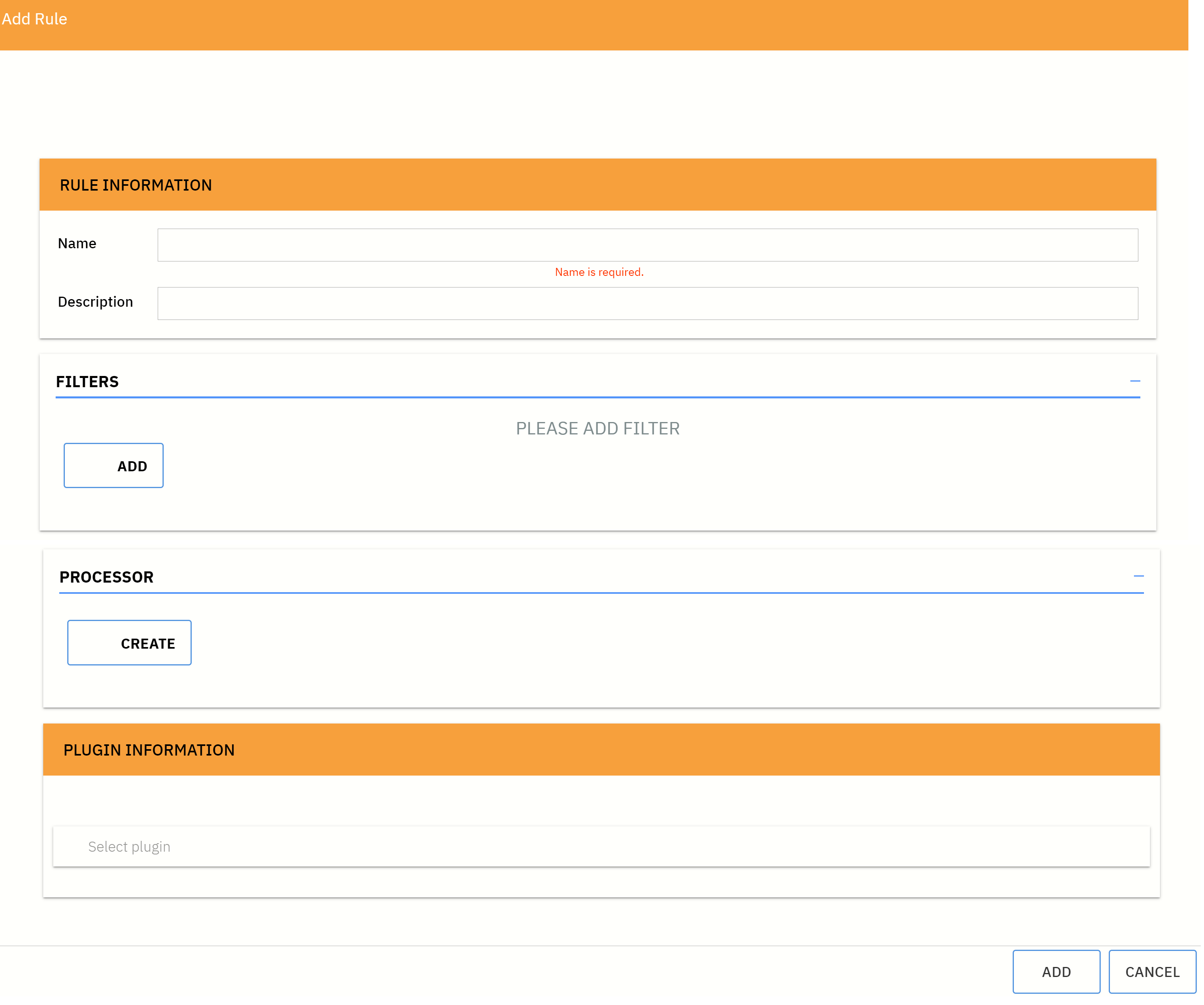
Create New Rule
Rules consists of three main components: Filters, Processor and Action.
In order to configure Rule, one need to specify at least one Filter and one Action.
- Name the rule and write a brief description about it.
Add Filter
Rule filter is responsible for filtering incoming messages.
-
Click button Add to add a filter.
-
Name the filter.
-
Click pull-down menu to select type of filter.
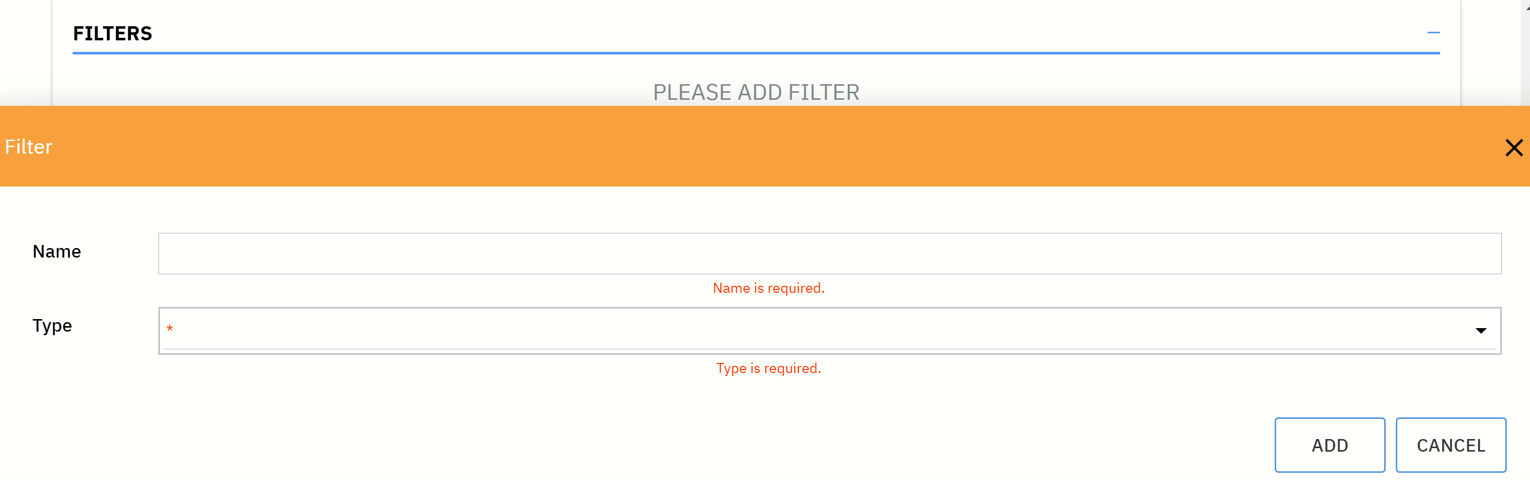
- Choose filter type accordingly.
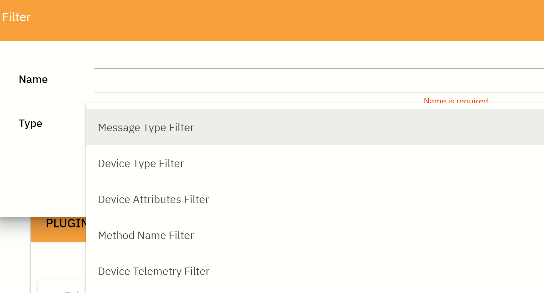
-
OIP platform provides the following rule filters:
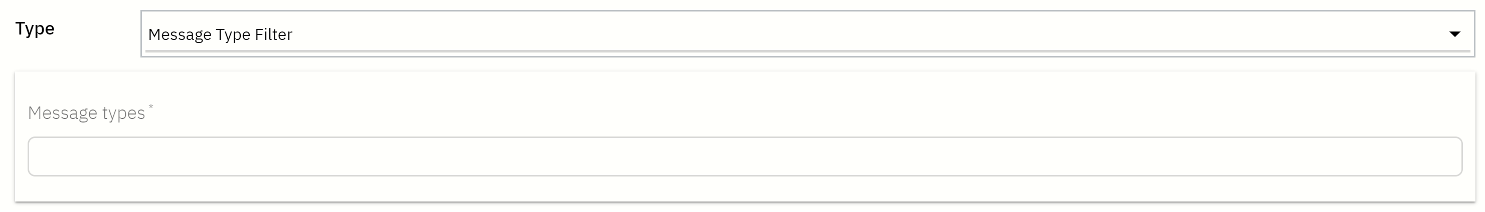
i. Message Type Filter - Allows to filter incoming messages by type
ii. Device Attributes Filter - Allows to filter incoming messages based on current device attributes. Filter can be written using Java script.
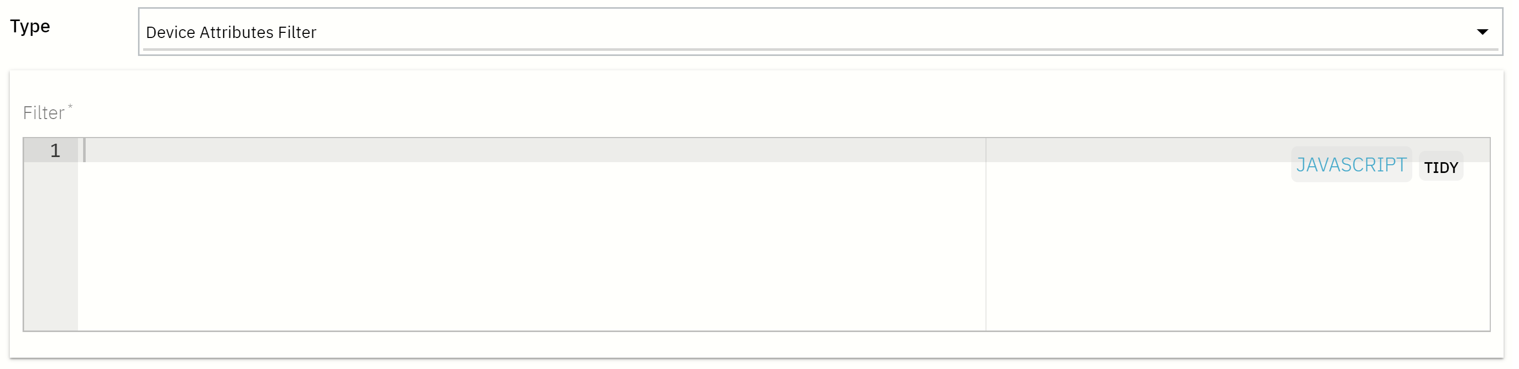
iii. Device Telemetry Filter - Allows to filter incoming “Post Telemetry” message based on it’s values. Filter can be written using Java script.
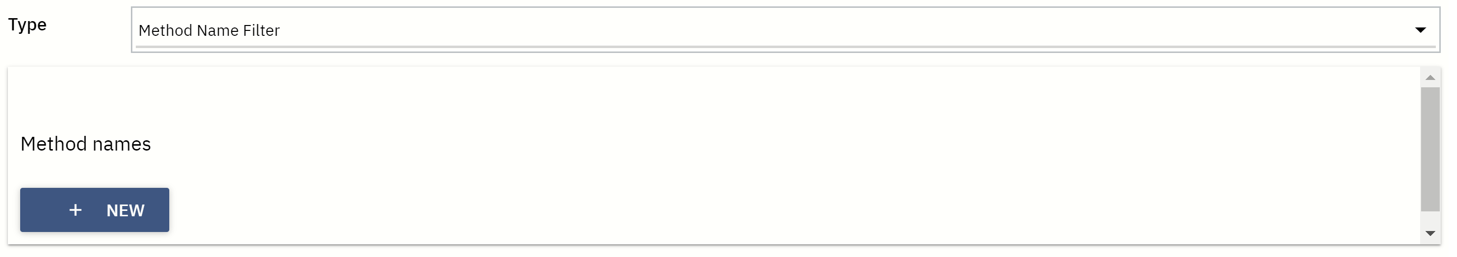
iv. Method Name Filter - Allows to filter incoming “RPC Request” message based on it’s method. RPC stands for Remote Procedure Calls.
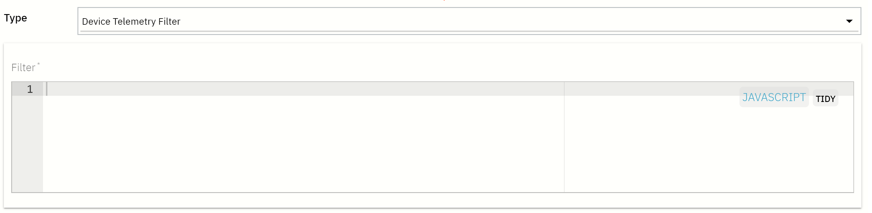
Create Processor
Rule Processor is responsible for processing incoming message and adding metadata to it. You can treat it as a function that has device attributes and message as parameters and returns certain metadata:

After type of filter is chosen, a window is appear to allow for user to write rule’s filter or add method/device type filter.
Add Plugin
Plugins allow you to configure and customize system behavior. Plugins are able: (i) to process messages from Rules (ii) provides APIs to integrate with your server-side application
-
Place pointer at Plugins menu at left side of the screen
-
Click plus sign at the bottom right side of the screen. Choose Create new plugin
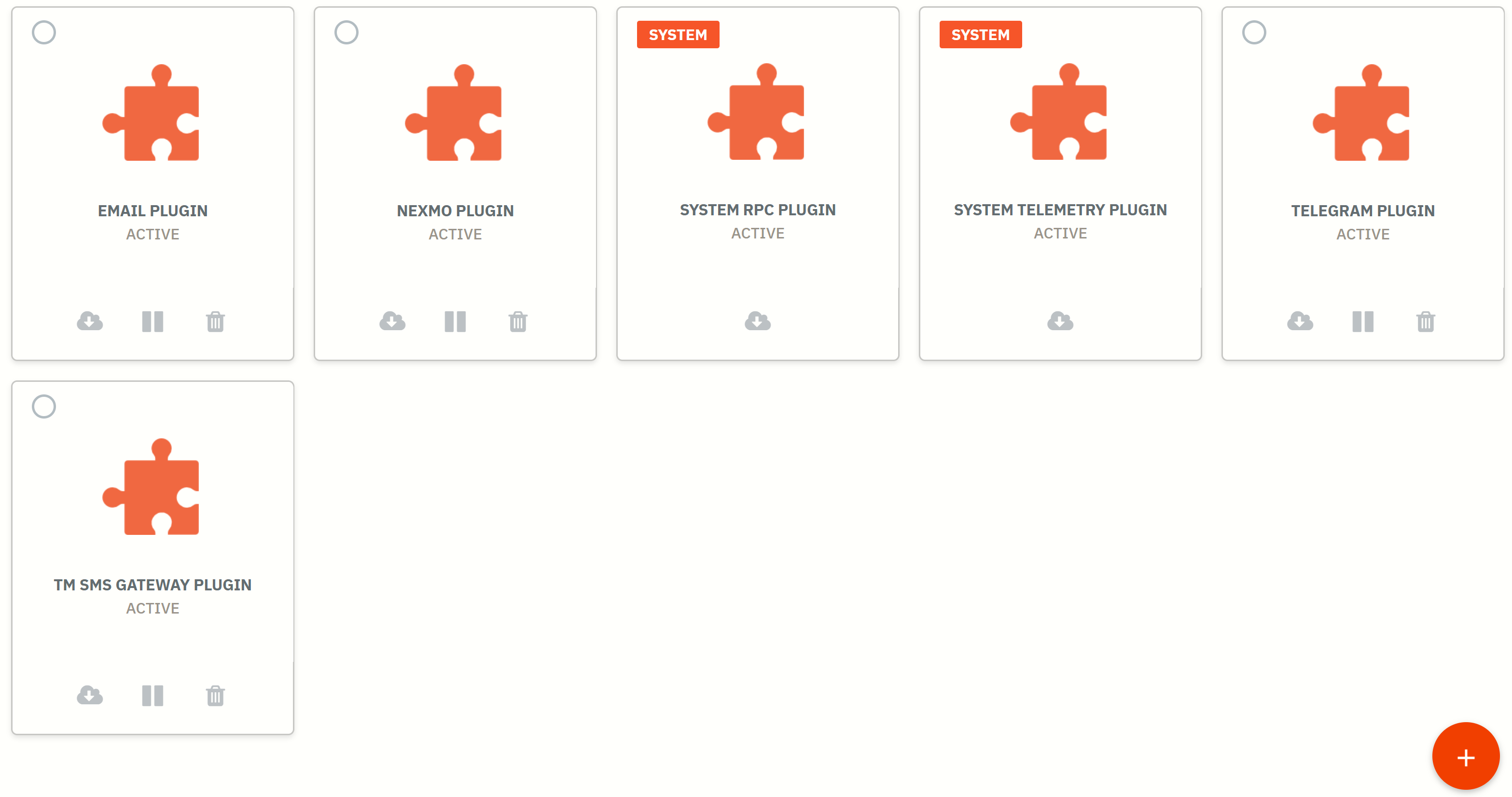
-
Write a name for the plugin and the click ADD button.
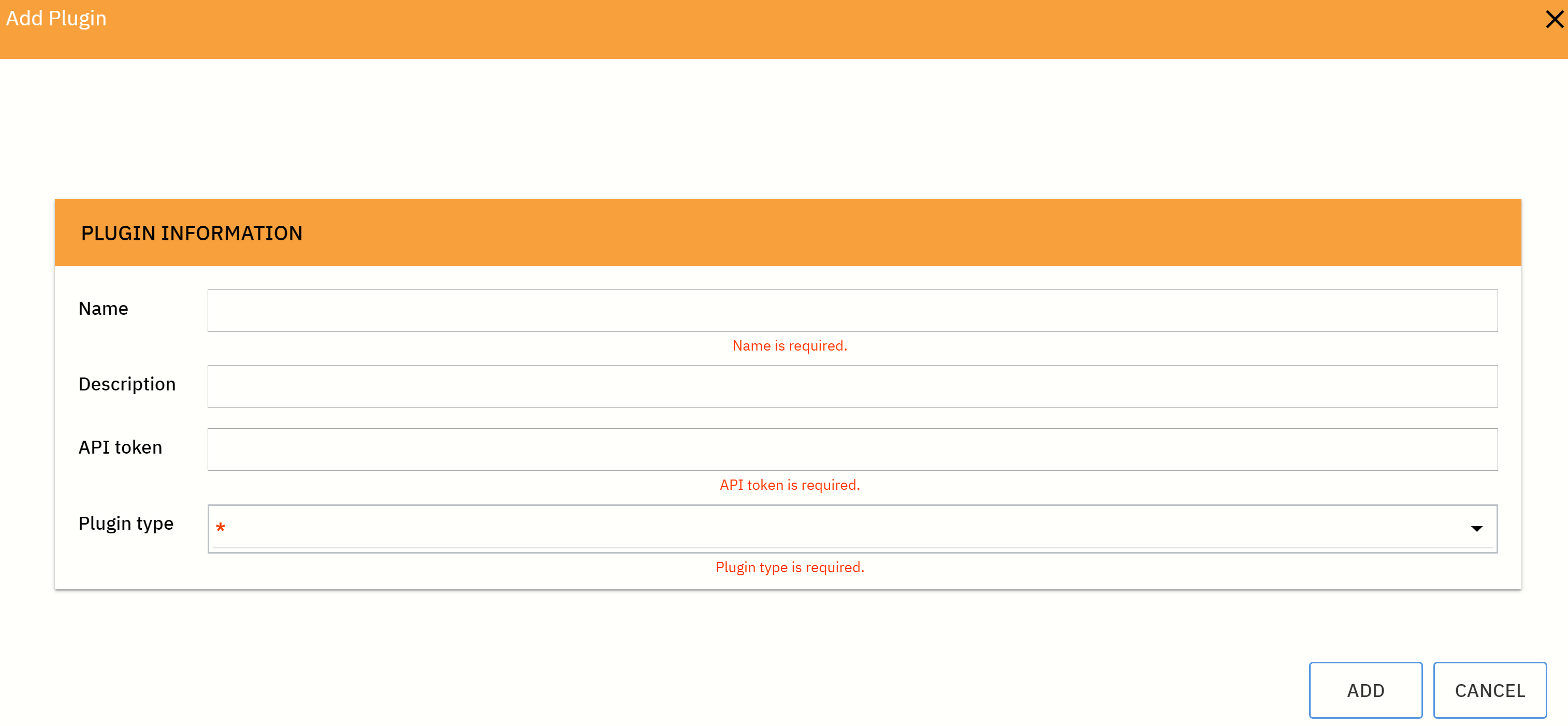
-
Choose one of plugin type as listed.
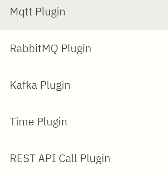
Bosch XDK110 – Push Sensor Data to OIP Service Creation Platform
- This guide provides both HTTPS and MQTT methods to push Bosch XDK110 https://xdk.bosch-connectivity.com/ja/overview sensor data to OIP Platform.
- First step is to create OIP account for Service Creation Platform (SCP) at https://signup.oip.tm.com.my/store/.
- There are 3 IoT devices to manage and create services upon successful registration.
- Then download and install Workbench 3.6.0 https://xdk.bosch-connectivity.com/ja/software-downloads.
- Full code for both HTTPS and MQTT are provided, and this guide is intended to provide instruction to setup a few necessary parameters.
- The code will push 3-axis accelerometer reading, magnetometer, 3-axis gyroscope, humidity, temperature, pressure and light intensity https://developer.bosch.com/web/xdk/enable-all-sensors-in-one.
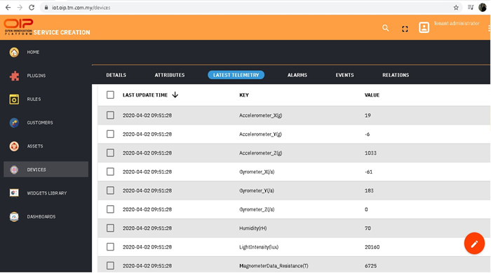
HTTPS Post
A complete guide to push XDK110 sensor data via HTTPS is here https://developer.bosch.com/web/xdk/https. Necessary steps to push XDK110 sensor data via HTTPS are as follow:
- Create a C project using an XDKApplicationTemplate:
File -> New -> Project -> XDK -> C Project -> Next -> select XDKApplicationTemplate
-
Full code for HTTPS post consists of C source code AppController_HTTPsPost.c and header file AppController_HTTPsPost.h
-
Before you can copy and paste to your AppController.c and AppController.h source, it is required to modify AppController_HTTPsPost.h as follow:
#define WLAN_SSID         "YourWifiNetwork" // replace with your WiFi SSID
#define WLAN_PSK          "YourWifiPasswork" // replace with your WiFi password
#define XDK_APP_DELAY      UINT32_C(30000)  // set XDK push interval
#define DEST_POST_PATH     "/api/v1/DeviceAccessToken/telemetry" // copy and paste your device access token
-
Then replace AppController.c with AppController_HTTPsPost.c and AppController.h with AppController_HTTPsPost.h
-
You are now done and ready to flash the code to your XDK110 device. Highlight project file, make sure device in bootloader mode and click flash.
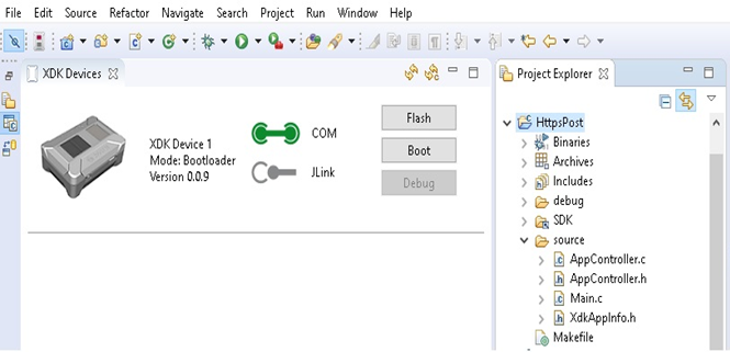
MQTT Post
A complete guide to push XDK110 sensor data via MQTT is here https://developer.bosch.com/web/xdk/mqtt Necessary steps to push XDK110 sensor data via HTTPS are as follow:
- Create a C project using an XDKApplicationTemplate:
File -> New -> Project -> XDK -> C Project -> Next -> select SendDataOverMQTT
Modify AppController_MQTT.h as follows:
#define WLAN_SSID                          "YourWifiNetwork" // replace with your WiFi SSID
#define WLAN_PSK                           "YourWifiPasswork" //replace with your WiFi password
#define APP_MQTT_DATA_PUBLISH_PERIODICITY   UINT32_C(10000) // set XDK push interval
#define APP_MQTT_CLIENT_USERNAME           "DeviceAccessToken" //paste your device access token
There are 3 code patches to be made:
- Open XDK_MQQT.h header file in XDK Workbench installation folder
- Click File and then Open File.
- Go to installation drive:\XDK-Workbench\XDK\SDK\xdk110\Common\include\Connectivity\XDK_MQTT.h
- Add the following first code patch to XDK_MQTT.h:
const char * device_uname;
const char * device_pwd;- Open XDK_MQQT.c header file in XDK Workbench installation folder
- Click File and then Open File.
- Go to installation drive:\XDK-Workbench\XDK\SDK\xdk110\Common\source\Connectivity\XDK_MQTT.c
- Add the following second code patch to XDK_MQTT.c:
  StringDescr_T username;
StringDescr_T password;- Add the following third code patch to XDK_MQTT.c:
  StringDescr_wrap(&username, mqttConnect->device_uname);
  MqttSession.username = username;
  StringDescr_wrap(&password, mqttConnect->device_pwd);
MqttSession.password = password;- Replace AppController.c with AppController_MQTT.c and AppController.h with AppController_MQTT.h
- You are done and ready to flash the code to your XDK110 device.
- Highlight project file and make sure device in bootloader mode and click flash.
Full Code AppController
AppController_HTPPsPost.h
Full Code 1: AppController_HTPPsPost.h
/*----------------------------------------------------------------------------*/
 /**  @file
 *
 *  Configuration header for the Test1_WlanNetworkManagement module.
 *
 * ****************************************************************************/

/* header definition ******************************************************** */
#ifndef APPCONTROLLER_H_
#define APPCONTROLLER_H_

/* local interface declaration ********************************************** */
#include "XDK_Utils.h"

/* local type and macro definitions */

/**  Depending on the configured mode, set  :
 *   - 0 for static IP application applicable only when WLAN_STATIC_IP is set true
 *   - 1 for DHCP IP application with callback,
 *   - 2 for DHCP IP application without callback,
 *   - 3 for deactivate
 **************************************************************************** */

#define USE_DHCP    1   // 1: DHCP; 0: Static IP
#define USE_WPA     1   // 1: WPA; 0: Open Access point

/**
 * SCAN_INTERVAL is the time interval between network scan.
 */
#define SCAN_INTERVAL     (5) /**< Time interval between network scan */

#warning Please provide your WLAN configurations below and remove this line.

/**
 * WLAN_SSID is the WIFI network name where user wants connect the XDK device.
 * Make sure to update the WLAN_PSK constant according to your required WIFI network.
 */
#define WLAN_SSID                           "YourWifiNetwork"

/**
 * WLAN_PSK is the WIFI router WPA/WPA2 password used at the Wifi network connection.
 * Make sure to update the WLAN_PSK constant according to your router password.
 */
#define WLAN_PSK                            "YourWifiPassword"

/**
 * WLAN_STATIC_IP is a boolean. If "true" then static IP will be assigned and if "false" then DHCP is used.
 */
#define WLAN_STATIC_IP                      false

/**
 * WLAN_IP_ADDR is the WIFI router WPA/WPA2 static IPv4 IP address (unused if WLAN_STATIC_IP is false)
 * Make sure to update the WLAN_IP_ADDR constant according to your required WIFI network,
 * if WLAN_STATIC_IP is "true".
 */
#define WLAN_IP_ADDR                        XDK_NETWORK_IPV4(0, 0, 0, 0)

/**
 * WLAN_GW_ADDR is the WIFI router WPA/WPA2 static IPv4 gateway address (unused if WLAN_STATIC_IP is false)
 * Make sure to update the WLAN_GW_ADDR constant according to your required WIFI network,
 * if WLAN_STATIC_IP is "true".
 */
#define WLAN_GW_ADDR                        XDK_NETWORK_IPV4(0, 0, 0, 0)

/**
 * WLAN_DNS_ADDR is the WIFI router WPA/WPA2 static IPv4 DNS address (unused if WLAN_STATIC_IP is false)
 * Make sure to update the WLAN_DNS_ADDR constant according to your required WIFI network,
 * if WLAN_STATIC_IP is "true".
 */
#define WLAN_DNS_ADDR                       XDK_NETWORK_IPV4(0, 0, 0, 0)

/**
 * WLAN_MASK is the WIFI router WPA/WPA2 static IPv4 mask address (unused if WLAN_STATIC_IP is false)
 * Make sure to update the WLAN_MASK constant according to your required WIFI network,
 * if WLAN_STATIC_IP is "true".
 */
#define WLAN_MASK                           XDK_NETWORK_IPV4(0, 0, 0, 0)

/* local function prototype declarations */

/**
 * APP_CONTROLLER_TX_DELAY is sensor data transmission in milliseconds
 */

#define XDK_APP_DELAY             UINT32_C(30000)


/**
 * APP_TEMPERATURE_OFFSET_CORRECTION is the Temperature sensor offset correction value (in mDegC).
 * Unused if APP_SENSOR_TEMP is false.
 * This is the Self heating, temperature correction factor.
 */

#define APP_TEMPERATURE_OFFSET_CORRECTION   (-3459)


// DEST_SERVER_HOST is the hostname of the webserver we will send HTTP requests to.
#define DEST_SERVER_HOST                "iot.oip.tm.com.my"


// DEST_SERVER_PORT is the TCP port to which we will send HTTP requests to.
#define DEST_SERVER_PORT                UINT16_C(443)


// DEST_POST_PATH is the path relative to the DEST_SERVER_HOST that we will send
//  the HTTP POST request to.

#define DEST_POST_PATH       "/api/v1/DeviceAccessToken/telemetry"

/**
 * @brief Gives control to the Application controller.
 *
 * @param[in] cmdProcessorHandle
 * Handle of the main command processor which shall be used based on the application needs
 *
 * @param[in] param2
 * Unused
 */

void AppController_Init(void * cmdProcessorHandle, uint32_t param2);

#endif /* APPCONTROLLER_H_ */

/***************************************************************************/
AppController_HTPPsPost.c
Full Code 2: AppController_HTPPsPost.c
/* --------------------------------------------------------------------------- |
 * INCLUDES & DEFINES ******************************************************** |
 * -------------------------------------------------------------------------- */
#include "XdkAppInfo.h"
#undef BCDS_MODULE_ID  // [i] Module ID define before including Basics package
#define BCDS_MODULE_ID XDK_APP_MODULE_ID_APP_CONTROLLER

/* own header files */
#include "AppController.h"

#include <stdio.h>
#include "BCDS_NetworkConfig.h"
#include "BCDS_WlanConnect.h"
#include "BCDS_CmdProcessor.h"
#include "FreeRTOS.h"

#include "simplelink.h"
#include "PIp.h"
#include "PAL_initialize_ih.h"

#include "XDK_Sensor.h"

/* --------------------------------------------------------------------------- |
 * MACROS ******************************************************************** |
 * -------------------------------------------------------------------------- */

/* --------------------------------------------------------------------------- |
 * HANDLES ******************************************************************* |
 * -------------------------------------------------------------------------- */

static CmdProcessor_T * AppCmdProcessor;

/* --------------------------------------------------------------------------- |
 * EXECUTING FUNCTIONS ******************************************************* |
 * -------------------------------------------------------------------------- */

/* --------------------------------------------------------------------------- |
* VARIABLES ***************************************************************** |
* -------------------------------------------------------------------------- */

static CmdProcessor_T *AppCmdProcessor;/**< Handle to store the main Command processor handle to be reused by ServalPAL thread */

static xTaskHandle AppControllerHandle = NULL;/**< OS thread handle for Application controller to be used by run-time blocking threads */


#define CA_FILE_NAME "oip.cer"
unsigned char digicert_root_crt[] = {
0x30, 0x82, 0x03, 0x5F, 0x30, 0x82, 0x02, 0x47, 0xA0, 0x03, 0x02, 0x01, 0x02, 0x02, 0x0B, 0x04, 0x00, 0x00, 0x00, 0x00, 0x01, 0x21, 0x58, 0x53, 0x08, 0xA2, 0x30, 0x0D, 0x06, 0x09, 0x2A, 0x86,    0x48, 0x86, 0xF7, 0x0D, 0x01, 0x01, 0x0B, 0x05, 0x00, 0x30, 0x4C, 0x31, 0x20, 0x30, 0x1E, 0x06,
0x03, 0x55, 0x04, 0x0B, 0x13, 0x17, 0x47, 0x6C, 0x6F, 0x62, 0x61, 0x6C, 0x53, 0x69, 0x67, 0x6E,    0x20, 0x52, 0x6F, 0x6F, 0x74, 0x20, 0x43, 0x41, 0x20, 0x2D, 0x20, 0x52, 0x33, 0x31, 0x13, 0x30,    0x11, 0x06, 0x03, 0x55, 0x04, 0x0A, 0x13, 0x0A, 0x47, 0x6C, 0x6F, 0x62, 0x61, 0x6C, 0x53, 0x69,
0x67, 0x6E, 0x31, 0x13, 0x30, 0x11, 0x06, 0x03, 0x55, 0x04, 0x03, 0x13, 0x0A, 0x47, 0x6C, 0x6F,    0x62, 0x61, 0x6C, 0x53, 0x69, 0x67, 0x6E, 0x30, 0x1E, 0x17, 0x0D, 0x30, 0x39, 0x30, 0x33, 0x31,    0x38, 0x31, 0x30, 0x30, 0x30, 0x30, 0x30, 0x5A, 0x17, 0x0D, 0x32, 0x39, 0x30, 0x33, 0x31, 0x38,
0x31, 0x30, 0x30, 0x30, 0x30, 0x30, 0x5A, 0x30, 0x4C, 0x31, 0x20, 0x30, 0x1E, 0x06, 0x03, 0x55,    0x04, 0x0B, 0x13, 0x17, 0x47, 0x6C, 0x6F, 0x62, 0x61, 0x6C, 0x53, 0x69, 0x67, 0x6E, 0x20, 0x52,    0x6F, 0x6F, 0x74, 0x20, 0x43, 0x41, 0x20, 0x2D, 0x20, 0x52, 0x33, 0x31, 0x13, 0x30, 0x11, 0x06,
0x03, 0x55, 0x04, 0x0A, 0x13, 0x0A, 0x47, 0x6C, 0x6F, 0x62, 0x61, 0x6C, 0x53, 0x69, 0x67, 0x6E,    0x31, 0x13, 0x30, 0x11, 0x06, 0x03, 0x55, 0x04, 0x03, 0x13, 0x0A, 0x47, 0x6C, 0x6F, 0x62, 0x61,    0x6C, 0x53, 0x69, 0x67, 0x6E, 0x30, 0x82, 0x01, 0x22, 0x30, 0x0D, 0x06, 0x09, 0x2A, 0x86, 0x48,
0x86, 0xF7, 0x0D, 0x01, 0x01, 0x01, 0x05, 0x00, 0x03, 0x82, 0x01, 0x0F, 0x00, 0x30, 0x82, 0x01,    0x0A, 0x02, 0x82, 0x01, 0x01, 0x00, 0xCC, 0x25, 0x76, 0x90, 0x79, 0x06, 0x78, 0x22, 0x16, 0xF5,    0xC0, 0x83, 0xB6, 0x84, 0xCA, 0x28, 0x9E, 0xFD, 0x05, 0x76, 0x11, 0xC5, 0xAD, 0x88, 0x72, 0xFC,
0x46, 0x02, 0x43, 0xC7, 0xB2, 0x8A, 0x9D, 0x04, 0x5F, 0x24, 0xCB, 0x2E, 0x4B, 0xE1, 0x60, 0x82,    0x46, 0xE1, 0x52, 0xAB, 0x0C, 0x81, 0x47, 0x70, 0x6C, 0xDD, 0x64, 0xD1, 0xEB, 0xF5, 0x2C, 0xA3,    0x0F, 0x82, 0x3D, 0x0C, 0x2B, 0xAE, 0x97, 0xD7, 0xB6, 0x14, 0x86, 0x10, 0x79, 0xBB, 0x3B, 0x13,
0x80, 0x77, 0x8C, 0x08, 0xE1, 0x49, 0xD2, 0x6A, 0x62, 0x2F, 0x1F, 0x5E, 0xFA, 0x96, 0x68, 0xDF,    0x89, 0x27, 0x95, 0x38, 0x9F, 0x06, 0xD7, 0x3E, 0xC9, 0xCB, 0x26, 0x59, 0x0D, 0x73, 0xDE, 0xB0,    0xC8, 0xE9, 0x26, 0x0E, 0x83, 0x15, 0xC6, 0xEF, 0x5B, 0x8B, 0xD2, 0x04, 0x60, 0xCA, 0x49, 0xA6,
0x28, 0xF6, 0x69, 0x3B, 0xF6, 0xCB, 0xC8, 0x28, 0x91, 0xE5, 0x9D, 0x8A, 0x61, 0x57, 0x37, 0xAC,    0x74, 0x14, 0xDC, 0x74, 0xE0, 0x3A, 0xEE, 0x72, 0x2F, 0x2E, 0x9C, 0xFB, 0xD0, 0xBB, 0xBF, 0xF5,    0x3D, 0x00, 0xE1, 0x06, 0x33, 0xE8, 0x82, 0x2B, 0xAE, 0x53, 0xA6, 0x3A, 0x16, 0x73, 0x8C, 0xDD,
0x41, 0x0E, 0x20, 0x3A, 0xC0, 0xB4, 0xA7, 0xA1, 0xE9, 0xB2, 0x4F, 0x90, 0x2E, 0x32, 0x60, 0xE9,    0x57, 0xCB, 0xB9, 0x04, 0x92, 0x68, 0x68, 0xE5, 0x38, 0x26, 0x60, 0x75, 0xB2, 0x9F, 0x77, 0xFF,    0x91, 0x14, 0xEF, 0xAE, 0x20, 0x49, 0xFC, 0xAD, 0x40, 0x15, 0x48, 0xD1, 0x02, 0x31, 0x61, 0x19,
0x5E, 0xB8, 0x97, 0xEF, 0xAD, 0x77, 0xB7, 0x64, 0x9A, 0x7A, 0xBF, 0x5F, 0xC1, 0x13, 0xEF, 0x9B,    0x62, 0xFB, 0x0D, 0x6C, 0xE0, 0x54, 0x69, 0x16, 0xA9, 0x03, 0xDA, 0x6E, 0xE9, 0x83, 0x93, 0x71,    0x76, 0xC6, 0x69, 0x85, 0x82, 0x17, 0x02, 0x03, 0x01, 0x00, 0x01, 0xA3, 0x42, 0x30, 0x40, 0x30,
0x0E, 0x06, 0x03, 0x55, 0x1D, 0x0F, 0x01, 0x01, 0xFF, 0x04, 0x04, 0x03, 0x02, 0x01, 0x06, 0x30,    0x0F, 0x06, 0x03, 0x55, 0x1D, 0x13, 0x01, 0x01, 0xFF, 0x04, 0x05, 0x30, 0x03, 0x01, 0x01, 0xFF,    0x30, 0x1D, 0x06, 0x03, 0x55, 0x1D, 0x0E, 0x04, 0x16, 0x04, 0x14, 0x8F, 0xF0, 0x4B, 0x7F, 0xA8,
0x2E, 0x45, 0x24, 0xAE, 0x4D, 0x50, 0xFA, 0x63, 0x9A, 0x8B, 0xDE, 0xE2, 0xDD, 0x1B, 0xBC, 0x30,    0x0D, 0x06, 0x09, 0x2A, 0x86, 0x48, 0x86, 0xF7, 0x0D, 0x01, 0x01, 0x0B, 0x05, 0x00, 0x03, 0x82,    0x01, 0x01, 0x00, 0x4B, 0x40, 0xDB, 0xC0, 0x50, 0xAA, 0xFE, 0xC8, 0x0C, 0xEF, 0xF7, 0x96, 0x54,
0x45, 0x49, 0xBB, 0x96, 0x00, 0x09, 0x41, 0xAC, 0xB3, 0x13, 0x86, 0x86, 0x28, 0x07, 0x33, 0xCA,    0x6B, 0xE6, 0x74, 0xB9, 0xBA, 0x00, 0x2D, 0xAE, 0xA4, 0x0A, 0xD3, 0xF5, 0xF1, 0xF1, 0x0F, 0x8A,    0xBF, 0x73, 0x67, 0x4A, 0x83, 0xC7, 0x44, 0x7B, 0x78, 0xE0, 0xAF, 0x6E, 0x6C, 0x6F, 0x03, 0x29,
0x8E, 0x33, 0x39, 0x45, 0xC3, 0x8E, 0xE4, 0xB9, 0x57, 0x6C, 0xAA, 0xFC, 0x12, 0x96, 0xEC, 0x53,    0xC6, 0x2D, 0xE4, 0x24, 0x6C, 0xB9, 0x94, 0x63, 0xFB, 0xDC, 0x53, 0x68, 0x67, 0x56, 0x3E, 0x83,    0xB8, 0xCF, 0x35, 0x21, 0xC3, 0xC9, 0x68, 0xFE, 0xCE, 0xDA, 0xC2, 0x53, 0xAA, 0xCC, 0x90, 0x8A,
0xE9, 0xF0, 0x5D, 0x46, 0x8C, 0x95, 0xDD, 0x7A, 0x58, 0x28, 0x1A, 0x2F, 0x1D, 0xDE, 0xCD, 0x00,    0x37, 0x41, 0x8F, 0xED, 0x44, 0x6D, 0xD7, 0x53, 0x28, 0x97, 0x7E, 0xF3, 0x67, 0x04, 0x1E, 0x15,    0xD7, 0x8A, 0x96, 0xB4, 0xD3, 0xDE, 0x4C, 0x27, 0xA4, 0x4C, 0x1B, 0x73, 0x73, 0x76, 0xF4, 0x17,
0x99, 0xC2, 0x1F, 0x7A, 0x0E, 0xE3, 0x2D, 0x08, 0xAD, 0x0A, 0x1C, 0x2C, 0xFF, 0x3C, 0xAB, 0x55,    0x0E, 0x0F, 0x91, 0x7E, 0x36, 0xEB, 0xC3, 0x57, 0x49, 0xBE, 0xE1, 0x2E, 0x2D, 0x7C, 0x60, 0x8B,    0xC3, 0x41, 0x51, 0x13, 0x23, 0x9D, 0xCE, 0xF7, 0x32, 0x6B, 0x94, 0x01, 0xA8, 0x99, 0xE7, 0x2C,
0x33, 0x1F, 0x3A, 0x3B, 0x25, 0xD2, 0x86, 0x40, 0xCE, 0x3B, 0x2C, 0x86, 0x78, 0xC9, 0x61, 0x2F,    0x14, 0xBA, 0xEE, 0xDB, 0x55, 0x6F, 0xDF, 0x84, 0xEE, 0x05, 0x09, 0x4D, 0xBD, 0x28, 0xD8, 0x72,    0xCE, 0xD3, 0x62, 0x50, 0x65, 0x1E, 0xEB, 0x92, 0x97, 0x83, 0x31, 0xD9, 0xB3, 0xB5, 0xCA, 0x47,
0x58, 0x3F, 0x5F };


/**
 * @brief Callback function called when interrupt occurs
 *
 * @param [in]  param1
 * Unused
 *
 * @param [in]  param2
 * Unused
 */
static void AccelAppCallback(void *param1, uint32_t param2);

/**
 * @brief Callback function called when interrupt occurs
 *
 * @param [in]  param1
 * Unused
 *
 * @param [in]  param2
 * Unused
 */
static void LightAppCallback(void *param1, uint32_t param2);

static Sensor_Setup_T SensorSetup =
        {
                .CmdProcessorHandle = NULL,
                .Enable =
                        {
                                .Accel = true,
                                .Mag = true,
                                .Gyro = true,
                                .Humidity = true,
                                .Temp = true,
                                .Pressure = true,
                                .Light = true,
                                .Noise = false,
                        },
                .Config =
                        {
                                .Accel =
                                        {
                                .Type = SENSOR_ACCEL_BMA280,
                                .IsRawData = false,
                                .IsInteruptEnabled = true,
                                .Callback = AccelAppCallback,
                                        },
                                .Gyro =
                                        {
                                .Type = SENSOR_GYRO_BMG160,
                                .IsRawData = false,
                                        },
                                .Mag =
                                        {
                                .IsRawData = false,
                                        },
                                .Light =
                                        {
                                .IsInteruptEnabled = true,
                                .Callback = LightAppCallback,
                                        },
                                .Temp =
                                        {
                               .OffsetCorrection = APP_TEMPERATURE_OFFSET_CORRECTION,
                                        },
                        },
        };/**< Sensor setup parameters */

/* global variables ********************************************************* */

/* inline functions ********************************************************* */

/* local functions ********************************************************** */

static void AccelAppCallback(void *param1, uint32_t param2)
{
    BCDS_UNUSED(param1);
    BCDS_UNUSED(param2);

    printf("Accelerometer sensor application callback received\r\n");
}

static void LightAppCallback(void *param1, uint32_t param2)
{
    BCDS_UNUSED(param1);
    BCDS_UNUSED(param2);

    printf("*******Light sensor application callback received*******\r\n");
}


void sendPostRequest(_i16 socketHandle, char* host, char* path)
{
  Retcode_T retcode = RETCODE_OK;
  Sensor_Value_T sensorValue;

 while (1)
 {
    retcode = RETCODE_OK;
    retcode = Sensor_GetData(&sensorValue);

    if (RETCODE_OK == retcode) {
    char sensor[1024];
    sprintf(sensor,"{\"Humidity(rH)\":%ld,"
                    "\"Pressure(hPa)\":%ld,"
                    "\"Temperature(C)\":%.2lf,"
                    "\"LightIntensity(lux)\":%ld,"
                    "\"MagnometerData_Resistance(T)\":%ld,"
                    "\"Accelerometer_X(g)\":%ld,"
                    "\"Accelerometer_Y(g)\":%ld,"
                    "\"Accelerometer_Z(g)\":%ld,"
                    "\"Gyrometer_X(/s)\":%ld,"
                    "\"Gyrometer_Y(/s)\":%ld,"
                    "\"Gyrometer_Z(/s)\":%ld}"
                    ,sensorValue.RH
                    ,sensorValue.Pressure
                    ,(sensorValue.Temp /= 1000)
                    ,sensorValue.Light
                    ,sensorValue.Mag.R
                    ,sensorValue.Accel.X
                    ,sensorValue.Accel.Y
                    ,sensorValue.Accel.Z
                    ,sensorValue.Gyro.X
                    ,sensorValue.Gyro.Y
                    ,sensorValue.Gyro.Z);

    char sendBuffer[1024];
    char recvBuffer[512];

    _i16 bytesSent = 0;
    _i16 bytesReceived = 0;

    //char* body = "{\"status\":\"true\"}";
    char* body = sensor;
    int length = 0;

    length += sprintf(sendBuffer+length, "POST %s HTTP/1.1\r\n",path);
    length += sprintf(sendBuffer+length, "Host: %s\r\n",host);
    //length += sprintf(sendBuffer+length, "Accept: */* \r\n");
    length += sprintf(sendBuffer+length, "Content-Length: %d\r\n",strlen(body));
    length += sprintf(sendBuffer+length, "Content-Type: application/json\r\n\r\n");

    length += sprintf(sendBuffer+length, body);
    length += sprintf(sendBuffer+length, "\r\n");

    printf("--- HTTPS Request --- \r\n");
    printf("%s", sendBuffer);
    printf("\r\n---------------\r\n");
    printf("\r\n---------------\r\n");
    bytesSent = sl_Send(socketHandle, (const void *) sendBuffer, length, 0 );
    if( bytesSent <= 0 ) {
    printf("sl_Send failed: %i\r\n", bytesSent);
    return;
    }

    /*printf("--- HTTPS Response --- \r\n");
       sl_Recv(socketHandle, recvBuffer, 512, 0);
       printf("%s \n\r",recvBuffer);
       printf("\r\n---------------\r\n");*/


    printf("--- HTTPS Response ---\r\n");
    printf("\r\n======\r\n");

    int linesPrinted = 0;

    do {
        bytesReceived = sl_Recv(socketHandle, recvBuffer, 512, 0);
        int lastStart = 0;
        int pos = 0;
        while (linesPrinted < 10 && pos < bytesReceived) { if
            (recvBuffer[pos] == '\n') { printf("%.*s", pos - lastStart - 1,
            recvBuffer + lastStart); printf("\r\n"); lastStart = pos;
            linesPrinted++; } pos++; } } while(bytesReceived > 0);

    if (linesPrinted == 10) {
        printf("...\r\n");
        }
        printf("\r\n======\r\n");
    }

 vTaskDelay(XDK_APP_DELAY);

 }

}

// Call this function after flashCertificate() in appInitSystem()
void connectServerSecure(void){
 // For the purpose of readability this code has no error handling.
 // The simplelink API provides return codes of the type _i32 that can be
 // checked for the value SL_RET_CODE_OK

 // Getting the IP address of HOST_NAME:
 Ip_Address_T destAddr = 0;
 PAL_getIpaddress((uint8_t*) DEST_SERVER_HOST, &destAddr);

 // Creating a Socket (socketHandle ≦ 0 indicates an error):
 _i16 socketHandle = sl_Socket(SL_AF_INET, SL_SOCK_STREAM, SL_SEC_SOCKET);

 // Adding the certificate to the socket:
 sl_SetSockOpt(
   socketHandle,
   SL_SOL_SOCKET,
   SL_SO_SECURE_FILES_CA_FILE_NAME,
   CA_FILE_NAME,
   strlen(CA_FILE_NAME)
 );

 // Configuration of the connection settings (IP, Port, etc.):
 SlSockAddrIn_t addr;
 addr.sin_family = SL_AF_INET;
 addr.sin_port = sl_Htons(443);
 addr.sin_addr.s_addr = destAddr;

 // Connecting:
 sl_Connect(socketHandle, ( SlSockAddr_t *)&addr, sizeof(SlSockAddrIn_t));

 //sendGetRequest(socketHandle, HOST_NAME, "");
 sendPostRequest(socketHandle, DEST_SERVER_HOST, DEST_POST_PATH);

 // Closing:
 sl_Close(socketHandle);
}

// Flash the Certificate BEFORE attempting to connect.

void flashCertificate(char *fileName, _u8* data, _u32 length) {
 // For the purpose of readability this code has no error handling.
 // The simplelink API provides return codes of the type _i32 that can be
 // checked for the value SL_RET_CODE_OK

 // The datetime is required for certificate validation:
 SlDateTime_t dateTime;
 dateTime.sl_tm_day = (_u32)4;
 dateTime.sl_tm_mon = (_u32)1;
 dateTime.sl_tm_year = (_u32)2019;
 dateTime.sl_tm_hour = (_u32)0;
 dateTime.sl_tm_min = (_u32)0;
 dateTime.sl_tm_sec = (_u32)0;

 sl_DevSet(
     SL_DEVICE_GENERAL_CONFIGURATION,
     SL_DEVICE_GENERAL_CONFIGURATION_DATE_TIME,
     sizeof(SlDateTime_t),
     (_u8 *)(&dateTime)
 );

 // If a file with the same name already exists, call this first:
 // sl_FsDel((_u8*) CA_FILE_NAME, 0)
 // The file handle should not be 0 after a file was successfully created:
 _i32 fileHandle = 0;

 sl_FsOpen((_u8*) fileName, FS_MODE_OPEN_CREATE(1024,
     _FS_FILE_PUBLIC_WRITE | _FS_FILE_PUBLIC_READ),NULL,&fileHandle);

 // If the file is longer than 1024 bytes, you need to loop the writing.
 // "length" contains the length of the certificate
 // "writtenLength" contains the amount of actually written bytes.
 //_i32 writtenLen = sl_FsWrite(fileHandle, 0, data, length);


 _u32 remainingLength = length;
 while(remainingLength > 0)
 {
     remainingLength -= (_u32) sl_FsWrite(fileHandle, length - remainingLength,data+(length - remainingLength),
            remainingLength > 1024 ? 1024 : remainingLength // equal to max(remainingLength, 1024)
                );
 }

 sl_FsClose(fileHandle, NULL, NULL, 0);
}


static void initWifi(void)
{
  /* initialize the Wi-Fi module */
  WlanConnect_Init();
}

static void setIPSettings(void) {
#if USE_DHCP
    NetworkConfig_SetIpDhcp(NULL);
#else
    NetworkConfig_IpSettings_T myIpSet;
    myIpSet.isDHCP = (uint8_t) NETWORKCONFIG_DHCP_DISABLED;
    myIpSet.ipV4 = NetworkConfig_Ipv4Value(192, 168, 0, 2);
    myIpSet.ipV4DnsServer = NetworkConfig_Ipv4Value(192, 168, 0, 1);
    myIpSet.ipV4Gateway = NetworkConfig_Ipv4Value(192, 168, 0, 1);
    myIpSet.ipV4Mask = NetworkConfig_Ipv4Value(255, 255, 255, 0);
    NetworkConfig_SetIpStatic(myIpSet);
#endif
}

static void connectWiFi(void){
    WlanConnect_SSID_T connectSSID = (WlanConnect_SSID_T) WLAN_SSID;
#if USE_WPA
    WlanConnect_PassPhrase_T connectPassPhrase = (WlanConnect_PassPhrase_T) WLAN_PSK;
    WlanConnect_WPA(connectSSID, connectPassPhrase, NULL);
#else
    status = WlanConnect_Open(connectSSID, NULL);
#endif // USE_WPA
}

static void printIP(void){
    NetworkConfig_IpSettings_T myIp;
    NetworkConfig_GetIpSettings(&myIp);

    // insert a delay here, if the IP is not properly printed
    printf("The IP was retrieved: %u.%u.%u.%u \n\r",
    (unsigned int) (NetworkConfig_Ipv4Byte(myIp.ipV4, 3)),
    (unsigned int) (NetworkConfig_Ipv4Byte(myIp.ipV4, 2)),
    (unsigned int) (NetworkConfig_Ipv4Byte(myIp.ipV4, 1)),
    (unsigned int) (NetworkConfig_Ipv4Byte(myIp.ipV4, 0)));
}

/* --------------------------------------------------------------------------- |
 * BOOTING- AND SETUP FUNCTIONS ********************************************** |
 * -------------------------------------------------------------------------- */

static void AppControllerEnable(void * param1, uint32_t param2)
{
   BCDS_UNUSED(param1);
   BCDS_UNUSED(param2);

   //connectServerSecure();

   Retcode_T retcode = Sensor_Enable();
   if (RETCODE_OK == retcode)
   {
       printf("Connect to OIP server with certificate and send the POST request\n");
       if (pdPASS != xTaskCreate(connectServerSecure, (const char * const ) "AppController", TASK_STACK_SIZE_APP_CONTROLLER, NULL, TASK_PRIO_APP_CONTROLLER, &AppControllerHandle))
       {
           retcode = RETCODE(RETCODE_SEVERITY_ERROR, RETCODE_OUT_OF_RESOURCES);
       }
   }
   if (RETCODE_OK != retcode)
   {
       printf("AppControllerEnable : Failed \r\n");
       Retcode_RaiseError(retcode);
       assert(0); /* To provide LED indication for the user */
   }
   Utils_PrintResetCause();

}

static void AppControllerSetup(void * param1, uint32_t param2)
{
    BCDS_UNUSED(param1);
    BCDS_UNUSED(param2);

    // Setup of the necessary module
    vTaskDelay(2500);
    initWifi();
    setIPSettings();
    connectWiFi();
    printIP();

    int digicert_root_crt_len = sizeof(digicert_root_crt)/sizeof(unsigned char);
    flashCertificate(CA_FILE_NAME, digicert_root_crt, digicert_root_crt_len);

    SensorSetup.CmdProcessorHandle = AppCmdProcessor;
    Retcode_T retcode = Sensor_Setup(&SensorSetup);


    if (RETCODE_OK == retcode)
    {
    retcode = CmdProcessor_Enqueue(AppCmdProcessor, AppControllerEnable, NULL, UINT32_C(0));
    }

    if (RETCODE_OK != retcode)
    {
        printf("AppControllerSetup : Failed \r\n");
        Retcode_RaiseError(retcode);
        assert(0);
    }
}

void AppController_Init(void * cmdProcessorHandle, uint32_t param2)
{
    BCDS_UNUSED(param2);

    Retcode_T retcode = RETCODE_OK;

    if (cmdProcessorHandle == NULL)
    {
        printf("AppController_Init : Command processor handle is NULL \r\n");
        retcode = RETCODE(RETCODE_SEVERITY_ERROR, RETCODE_NULL_POINTER);
    }
    else
    {
        AppCmdProcessor = (CmdProcessor_T *) cmdProcessorHandle;
        retcode = CmdProcessor_Enqueue(AppCmdProcessor, AppControllerSetup, NULL, UINT32_C(0));
    }
    if (RETCODE_OK != retcode)
    {
        Retcode_RaiseError(retcode);
        assert(0);
    }
}
AppController_MQTT.h
Full Code 3: AppController_MQTT.h
/*----------------------------------------------------------------------------*/

/**
 * @file
 *
 * @brief Configuration header for the AppController.c file.
 *
 */

/* header definition ******************************************************** */
#ifndef APPCONTROLLER_H_
#define APPCONTROLLER_H_

/* local interface declaration ********************************************** */
#include "XDK_Utils.h"

/* local type and macro definitions */

/* WLAN configurations ****************************************************** */

#warning Please configure your WLAN below and remove this line.

/**
 * WLAN_SSID is the WIFI network name where user wants connect the XDK device.
 * Make sure to update the WLAN_PSK constant according to your required WIFI network.
 */
#define WLAN_SSID                           "YourWifiNetwork"

/**
 * WLAN_PSK is the WIFI router WPA/WPA2 password used at the Wifi network connection.
 * Make sure to update the WLAN_PSK constant according to your router password.
 */
#define WLAN_PSK                            "YourWifiPassword"

/**
 * WLAN_STATIC_IP is a boolean. If "true" then static IP will be assigned and if "false" then DHCP is used.
 */
#define WLAN_STATIC_IP                      false

/**
 * WLAN_IP_ADDR is the WIFI router WPA/WPA2 static IPv4 IP address (unused if WLAN_STATIC_IP is false)
 * Make sure to update the WLAN_IP_ADDR constant according to your required WIFI network,
 * if WLAN_STATIC_IP is "true".
 */
#define WLAN_IP_ADDR                        XDK_NETWORK_IPV4(0, 0, 0, 0)

/**
 * WLAN_GW_ADDR is the WIFI router WPA/WPA2 static IPv4 gateway address (unused if WLAN_STATIC_IP is false)
 * Make sure to update the WLAN_GW_ADDR constant according to your required WIFI network,
 * if WLAN_STATIC_IP is "true".
 */
#define WLAN_GW_ADDR                        XDK_NETWORK_IPV4(0, 0, 0, 0)

/**
 * WLAN_DNS_ADDR is the WIFI router WPA/WPA2 static IPv4 DNS address (unused if WLAN_STATIC_IP is false)
 * Make sure to update the WLAN_DNS_ADDR constant according to your required WIFI network,
 * if WLAN_STATIC_IP is "true".
 */
#define WLAN_DNS_ADDR                       XDK_NETWORK_IPV4(0, 0, 0, 0)

/**
 * WLAN_MASK is the WIFI router WPA/WPA2 static IPv4 mask address (unused if WLAN_STATIC_IP is false)
 * Make sure to update the WLAN_MASK constant according to your required WIFI network,
 * if WLAN_STATIC_IP is "true".
 */
#define WLAN_MASK                           XDK_NETWORK_IPV4(0, 0, 0, 0)

/* SNTP configurations ****************************************************** */

/**
 * SNTP_SERVER_URL is the SNTP server URL.
 */
#define SNTP_SERVER_URL                     "YourSNTPServerURL"

/**
 * SNTP_SERVER_PORT is the SNTP server port number.
 */
#define SNTP_SERVER_PORT                    UINT16_C(123)

/* MQTT server configurations *********************************************** */

/**
 * APP_MQTT_BROKER_HOST_URL is the MQTT broker host address URL.
 */
#define APP_MQTT_BROKER_HOST_URL            "iot.oip.tm.com.my"

#define APP_MQTT_CLIENT_USERNAME            "DeviceAccessToken"

/**
 * APP_MQTT_BROKER_HOST_PORT is the MQTT broker host port.
 */

#define APP_MQTT_BROKER_HOST_PORT           UINT16_C(1883)


/**
 * APP_MQTT_CLIENT_ID is the device name
 */
#define APP_MQTT_CLIENT_ID                  "XDK110"

/**
 * APP_MQTT_TOPIC is the topic to subscribe and publish
 */
#define APP_MQTT_TOPIC                      "v1/devices/me/telemetry"

#warning Configure APP_MQTT_SECURE_ENABLE to 1 to enable the MQTT with secure communication.\
    Otherwise Communication will happen without security. \
    Also provide the right server certificate in the ServerCA.h file. \
    Remove this line to avoid warnings.
/**
 * APP_MQTT_SECURE_ENABLE is a macro to enable MQTT with security
 */
#define APP_MQTT_SECURE_ENABLE              0

/**
 * APP_MQTT_DATA_PUBLISH_PERIODICITY is time for MQTT to publish the sensor data
 */
#define APP_MQTT_DATA_PUBLISH_PERIODICITY   UINT32_C(10000)

/* local function prototype declarations */

/* local module global variable declarations */

/* local inline function definitions */

/**
 * @brief Gives control to the Application controller.
 *
 * @param[in] cmdProcessorHandle
 * Handle of the main command processor which shall be used based on the application needs
 *
 * @param[in] param2
 * Unused
 */
void AppController_Init(void * cmdProcessorHandle, uint32_t param2);

#endif /* APPCONTROLLER_H_ */

/***************************************************************************/
AppController_MQTT.c
Full Code 4: AppController_MQTT.c
/*----------------------------------------------------------------------------*/
/**
 * @ingroup APPS_LIST
 *
 * @defgroup SEND_DATA_OVER_MQTT MQTT
 * @{
 *
 * @brief Demo application for using MQTT protocol.
 *
 * @details This example shows how to use the MQTT protocol to transfer the environmental data.
 *
 * You need to add your WLAN-Credentials in \ref AppController.h\n
 * When running the program keep the USB plugged in to the PC.
 * You can see in the console output of the XDK-Workbench the content of the environmental data.
 *
 * @file
 **/
/* module includes ********************************************************** */

/* own header files */
#include "XdkAppInfo.h"
#undef BCDS_MODULE_ID  /* Module ID define before including Basics package*/
#define BCDS_MODULE_ID XDK_APP_MODULE_ID_APP_CONTROLLER

/* own header files */
#include "AppController.h"

/* system header files */
#include <stdio.h>

/* additional interface header files */
#include "BCDS_BSP_Board.h"
#include "BCDS_CmdProcessor.h"
#include "BCDS_WlanNetworkConfig.h"
#include "BCDS_WlanNetworkConnect.h"
#include "BCDS_Assert.h"
#include "XDK_Utils.h"
#include "XDK_WLAN.h"
#include "XDK_MQTT.h"
#include "XDK_Sensor.h"
#include "XDK_SNTP.h"
#include "XDK_ServalPAL.h"
#include "FreeRTOS.h"
#include "task.h"

/* constant definitions ***************************************************** */

#define MQTT_CONNECT_TIMEOUT_IN_MS                  UINT32_C(60000)/**< Macro for MQTT connection timeout in milli-second */

#define MQTT_SUBSCRIBE_TIMEOUT_IN_MS                UINT32_C(20000)/**< Macro for MQTT subscription timeout in milli-second */

#define MQTT_PUBLISH_TIMEOUT_IN_MS                  UINT32_C(20000)/**< Macro for MQTT publication timeout in milli-second */

#define APP_TEMPERATURE_OFFSET_CORRECTION           (-3459)/**< Macro for static temperature offset correction. Self heating, temperature correction factor */

#define APP_MQTT_DATA_BUFFER_SIZE                   UINT32_C(256)/**< macro for data size of incoming subscribed and published messages */

#if APP_MQTT_SECURE_ENABLE
#define APP_RESPONSE_FROM_SNTP_SERVER_TIMEOUT       UINT32_C(10000)/**< Timeout for SNTP server time sync */
#endif /* APP_MQTT_SECURE_ENABLE */

/* local variables ********************************************************** */

static WLAN_Setup_T WLANSetupInfo =
        {
                .IsEnterprise = false,
                .IsHostPgmEnabled = false,
                .SSID = WLAN_SSID,
                .Username = WLAN_PSK,
                .Password = WLAN_PSK,
                .IsStatic = WLAN_STATIC_IP,
                .IpAddr = WLAN_IP_ADDR,
                .GwAddr = WLAN_GW_ADDR,
                .DnsAddr = WLAN_DNS_ADDR,
                .Mask = WLAN_MASK,
        };/**< WLAN setup parameters */

static Sensor_Setup_T SensorSetup =
        {
                .CmdProcessorHandle = NULL,
                .Enable =
                        {
                                .Accel = true,
                                .Mag = true,
                                .Gyro = true,
                                .Humidity = true,
                                .Temp = true,
                                .Pressure = true,
                                .Light = true,
                                .Noise = false,
                        },
                .Config =
                        {
                                .Accel =
                                        {
                                .Type = SENSOR_ACCEL_BMA280,
                                .IsRawData = false,
                                .IsInteruptEnabled = false,
                                .Callback = NULL,
                                        },
                                .Gyro =
                                        {
                                .Type = SENSOR_GYRO_BMG160,
                                .IsRawData = false,
                                        },
                                .Mag =
                                        {
                                .IsRawData = false
                                        },
                                .Light =
                                        {
                                .IsInteruptEnabled = false,
                                .Callback = NULL,
                                        },
                                .Temp =
                                        {
                                .OffsetCorrection = APP_TEMPERATURE_OFFSET_CORRECTION,
                                        },
                        },
        };/**< Sensor setup parameters */

#if APP_MQTT_SECURE_ENABLE
static SNTP_Setup_T SNTPSetupInfo =
        {
                .ServerUrl = SNTP_SERVER_URL,
                .ServerPort = SNTP_SERVER_PORT,
        };/**< SNTP setup parameters */
#endif /* APP_MQTT_SECURE_ENABLE */

static MQTT_Setup_T MqttSetupInfo =
        {
                .MqttType = MQTT_TYPE_SERVALSTACK,
                .IsSecure = APP_MQTT_SECURE_ENABLE,
        };/**< MQTT setup parameters */

static MQTT_Connect_T MqttConnectInfo =
        {
                .device_uname = APP_MQTT_CLIENT_USERNAME,
                .device_pwd ="",

                .ClientId = APP_MQTT_CLIENT_ID,
                .BrokerURL = APP_MQTT_BROKER_HOST_URL,
                .BrokerPort = APP_MQTT_BROKER_HOST_PORT,
                .CleanSession = true,
                .KeepAliveInterval = 100,
        };/**< MQTT connect parameters */

static void AppMQTTSubscribeCB(MQTT_SubscribeCBParam_T param);

static MQTT_Subscribe_T MqttSubscribeInfo =
        {
                .Topic = APP_MQTT_TOPIC,
                .QoS = 1UL,
                .IncomingPublishNotificationCB = AppMQTTSubscribeCB,
        };/**< MQTT subscribe parameters */

static MQTT_Publish_T MqttPublishInfo =
        {
                .Topic = APP_MQTT_TOPIC,
                .QoS = 1UL,
                .Payload = NULL,
                .PayloadLength = 0UL,
        };/**< MQTT publish parameters */

static uint32_t AppIncomingMsgCount = 0UL;/**< Incoming message count */

static char AppIncomingMsgTopicBuffer[APP_MQTT_DATA_BUFFER_SIZE];/**< Incoming message topic buffer */

static char AppIncomingMsgPayloadBuffer[APP_MQTT_DATA_BUFFER_SIZE];/**< Incoming message payload buffer */

static CmdProcessor_T * AppCmdProcessor;/**< Handle to store the main Command processor handle to be used by run-time event driven threads */

static xTaskHandle AppControllerHandle = NULL;/**< OS thread handle for Application controller to be used by run-time blocking threads */

/* global variables ********************************************************* */

/* inline functions ********************************************************* */

/* local functions ********************************************************** */

static void AppMQTTSubscribeCB(MQTT_SubscribeCBParam_T param)
{
    AppIncomingMsgCount++;
    memset(AppIncomingMsgTopicBuffer, 0,
    sizeof(AppIncomingMsgTopicBuffer));
    memset(AppIncomingMsgPayloadBuffer, 0,
    sizeof(AppIncomingMsgPayloadBuffer));

    if (param.PayloadLength < sizeof(AppIncomingMsgPayloadBuffer))
    {
        strncpy(AppIncomingMsgPayloadBuffer, (const char *) param.Payload,
        param.PayloadLength);
    }
    else
    {
        strncpy(AppIncomingMsgPayloadBuffer, (const char *) param.Payload,
       (sizeof(AppIncomingMsgPayloadBuffer) - 1U));
    }
    if (param.TopicLength < (int) sizeof(AppIncomingMsgTopicBuffer))
    {
        strncpy(AppIncomingMsgTopicBuffer, param.Topic, param.TopicLength);
    }
    else
    {
        strncpy(AppIncomingMsgTopicBuffer, param.Topic,
        (sizeof(AppIncomingMsgTopicBuffer) - 1U));
    }

    printf("AppMQTTSubscribeCB : #%d, Incoming Message:\r\n"
            "\tTopic: %s\r\n"
            "\tPayload: \r\n\"\"\"\r\n%s\r\n\"\"\"\r\n", (int) AppIncomingMsgCount,
            AppIncomingMsgTopicBuffer, AppIncomingMsgPayloadBuffer);
}

/**
 * @brief This will validate the WLAN network connectivity
 *
 * If there is no connectivity then it will scan for the given network and try to reconnect
 *
 * @return  RETCODE_OK on success, or an error code otherwise.
 */
static Retcode_T AppControllerValidateWLANConnectivity(void)
{
    Retcode_T retcode = RETCODE_OK;
    WlanNetworkConnect_IpStatus_T nwStatus;

    nwStatus = WlanNetworkConnect_GetIpStatus();
    if (WLANNWCT_IPSTATUS_CT_AQRD != nwStatus)
    {
#if APP_MQTT_SECURE_ENABLE
        static bool isSntpDisabled = false;
        if (false == isSntpDisabled)
        {
            retcode = SNTP_Disable();
        }
        if (RETCODE_OK == retcode)
        {
            isSntpDisabled = true;
            retcode = WLAN_Reconnect();
        }
        if (RETCODE_OK == retcode)
        {
            retcode = SNTP_Enable();
        }
#else
        retcode = WLAN_Reconnect();
#endif /* APP_MQTT_SECURE_ENABLE */
    }
    return retcode;
}

/**
 * @brief Responsible for controlling the send data over MQTT application control flow.
 *
 * - Synchronize SNTP time stamp for the system if MQTT communication is secure
 * - Connect to MQTT broker
 * - Subscribe to MQTT topic
 * - Read environmental sensor data
 * - Publish data periodically for a MQTT topic
 *
 * @param[in] pvParameters
 * Unused
 */
static void AppControllerFire(void* pvParameters)
{
    BCDS_UNUSED(pvParameters);

    Retcode_T retcode = RETCODE_OK;
    Sensor_Value_T sensorValue;
    char publishBuffer[APP_MQTT_DATA_BUFFER_SIZE];
    const char *publishDataFormat = "{\r\tAccelerometer_X(g) : %ld,"
                            "\r\tAccelerometer_Y(g) : %ld,"
                            "\r\tAccelerometer_Z(g) :%ld,"
                                    "\r\tMagnometerData_Resistance(T) : %ld,"
                            "\r\tGyrometer_X(/s) : %ld,"
                              "\r\tGyrometer_Y(/s) : %ld,"
                            "\r\tGyrometer_Z(/s) : %ld,"
                            "\r\tHumidity(rH) : %ld,"
                          "\r\tPressure(hPa) : %ld,"
                              "\r\tTemperature(C) : %f,"
                            "\r\tLightIntensity(lux) : %ld\n}";


    memset(&sensorValue, 0x00, sizeof(sensorValue));
#if APP_MQTT_SECURE_ENABLE

    uint64_t sntpTimeStampFromServer = 0UL;

    /* We Synchronize the node with the SNTP server for time-stamp.
     * Since there is no point in doing a HTTPS communication without a valid time */
    do
    {
        retcode = SNTP_GetTimeFromServer(&sntpTimeStampFromServer,
        APP_RESPONSE_FROM_SNTP_SERVER_TIMEOUT);
        if ((RETCODE_OK != retcode) || (0UL == sntpTimeStampFromServer))
        {
            printf("AppControllerFire : SNTP server time was not
                    synchronized. Retrying...\r\n");
        }
    } while (0UL == sntpTimeStampFromServer);

    BCDS_UNUSED(sntpTimeStampFromServer); /* Copy of sntpTimeStampFromServer will be used be HTTPS for TLS handshake */
#endif /* APP_MQTT_SECURE_ENABLE */

    if (RETCODE_OK == retcode)
    {
        retcode = MQTT_ConnectToBroker(&MqttConnectInfo, MQTT_CONNECT_TIMEOUT_IN_MS);
        if (RETCODE_OK != retcode)
        {
            printf("AppControllerFire : MQTT connection to the broker failed \n\r");
        }
    }

    if (RETCODE_OK == retcode)
    {
        retcode = MQTT_SubsribeToTopic(&MqttSubscribeInfo, MQTT_SUBSCRIBE_TIMEOUT_IN_MS);
        if (RETCODE_OK != retcode)
        {
            printf("AppControllerFire : MQTT subscribe failed \n\r");
        }
    }

    if (RETCODE_OK != retcode)
    {
        /* We raise error and still proceed to publish data periodically */
        Retcode_RaiseError(retcode);
        vTaskSuspend(NULL);
    }

    /* A function that implements a task must not exit or attempt to return to
     its caller function as there is nothing to return to. */
    while (1)
    {
        /* Resetting / clearing the necessary buffers / variables for re-use */
        retcode = RETCODE_OK;

        /* Check whether the WLAN network connection is available */
        retcode = AppControllerValidateWLANConnectivity();
        if (RETCODE_OK == retcode)
        {
            /* Check for MQTT broker connection */
            retcode = MQTT_IsConnected();
            if (RETCODE_OK != retcode)
            {
                printf("AppControllerFire : Re-connecting with MQTT broker... \n\r");
                retcode = MQTT_ConnectToBroker(&MqttConnectInfo, MQTT_CONNECT_TIMEOUT_IN_MS);
                if (RETCODE_OK == retcode)
                {
                    retcode = MQTT_SubsribeToTopic(&MqttSubscribeInfo, MQTT_SUBSCRIBE_TIMEOUT_IN_MS);
                }
            }
        }
        if (RETCODE_OK == retcode)
        {
            retcode = Sensor_GetData(&sensorValue);
        }
        if (RETCODE_OK == retcode)
        {
            int32_t length = snprintf((char *) publishBuffer, APP_MQTT_DATA_BUFFER_SIZE, publishDataFormat,
                     (long int) sensorValue.Accel.X,
                     (long int) sensorValue.Accel.Y,
                     (long int) sensorValue.Accel.Z,
                     (long int) sensorValue.Mag.R,
                     (long int) sensorValue.Gyro.X,
                     (long int) sensorValue.Gyro.Y,
                     (long int) sensorValue.Gyro.Z,
                     (long int) sensorValue.RH,
                       (long int) sensorValue.Pressure,
                     (sensorValue.Temp /= 1000),
                     (long int) sensorValue.Light);

            MqttPublishInfo.Payload = publishBuffer;
            MqttPublishInfo.PayloadLength = length;

            retcode = MQTT_PublishToTopic(&MqttPublishInfo, MQTT_PUBLISH_TIMEOUT_IN_MS);
            if (RETCODE_OK != retcode)
            {
                printf("AppControllerFire : MQTT publish failed \n\r");
            }
        }
        if (RETCODE_OK != retcode)
        {
            Retcode_RaiseError(retcode);
        }
        vTaskDelay(APP_MQTT_DATA_PUBLISH_PERIODICITY);
    }
}

/**
 * @brief To enable the necessary modules for the application
 * - WLAN
 * - ServalPAL
 * - SNTP (if secure communication)
 * - MQTT
 * - Sensor
 *
 * @param[in] param1
 * Unused
 *
 * @param[in] param2
 * Unused
 */
static void AppControllerEnable(void * param1, uint32_t param2)
{
    BCDS_UNUSED(param1);
    BCDS_UNUSED(param2);

    Retcode_T retcode = WLAN_Enable();
    if (RETCODE_OK == retcode)
    {
        retcode = ServalPAL_Enable();
    }
#if APP_MQTT_SECURE_ENABLE
    if (RETCODE_OK == retcode)
    {
        retcode = SNTP_Enable();
    }
#endif /* APP_MQTT_SECURE_ENABLE */
    if (RETCODE_OK == retcode)
    {
        retcode = MQTT_Enable();
    }
    if (RETCODE_OK == retcode)
    {
        retcode = Sensor_Enable();
    }
    if (RETCODE_OK == retcode)
    {
        if (pdPASS != xTaskCreate(AppControllerFire, (const char * const ) "AppController", TASK_STACK_SIZE_APP_CONTROLLER, NULL, TASK_PRIO_APP_CONTROLLER, &AppControllerHandle))
        {
            retcode = RETCODE(RETCODE_SEVERITY_ERROR, RETCODE_OUT_OF_RESOURCES);
        }
    }
    if (RETCODE_OK != retcode)
    {
        printf("AppControllerEnable : Failed \r\n");
        Retcode_RaiseError(retcode);
        assert(0); /* To provide LED indication for the user */
    }
    Utils_PrintResetCause();
}

/**
 * @brief To setup the necessary modules for the application
 * - WLAN
 * - ServalPAL
 * - SNTP (if secure communication)
 * - MQTT
 * - Sensor
 *
 * @param[in] param1
 * Unused
 *
 * @param[in] param2
 * Unused
 */
static void AppControllerSetup(void * param1, uint32_t param2)
{
    BCDS_UNUSED(param1);
    BCDS_UNUSED(param2);

    Retcode_T retcode = WLAN_Setup(&WLANSetupInfo);
    if (RETCODE_OK == retcode)
    {
        retcode = ServalPAL_Setup(AppCmdProcessor);
    }
#if APP_MQTT_SECURE_ENABLE
    if (RETCODE_OK == retcode)
    {
        retcode = SNTP_Setup(&SNTPSetupInfo);
    }
#endif /* APP_MQTT_SECURE_ENABLE */
    if (RETCODE_OK == retcode)
    {
        retcode = MQTT_Setup(&MqttSetupInfo);
    }
    if (RETCODE_OK == retcode)
    {
        SensorSetup.CmdProcessorHandle = AppCmdProcessor;
        retcode = Sensor_Setup(&SensorSetup);
    }
    if (RETCODE_OK == retcode)
    {
        retcode = CmdProcessor_Enqueue(AppCmdProcessor, AppControllerEnable, NULL, UINT32_C(0));
    }
    if (RETCODE_OK != retcode)
    {
        printf("AppControllerSetup : Failed \r\n");
        Retcode_RaiseError(retcode);
        assert(0); /* To provide LED indication for the user */
    }
}

/* global functions ********************************************************* */

/** Refer interface header for description */
void AppController_Init(void * cmdProcessorHandle, uint32_t param2)
{
    BCDS_UNUSED(param2);

    Retcode_T retcode = RETCODE_OK;

    if (cmdProcessorHandle == NULL)
    {
        printf("AppController_Init : Command processor handle is NULL \r\n");
        retcode = RETCODE(RETCODE_SEVERITY_ERROR, RETCODE_NULL_POINTER);
    }
    else
    {
        AppCmdProcessor = (CmdProcessor_T *) cmdProcessorHandle;
        retcode = CmdProcessor_Enqueue(AppCmdProcessor, AppControllerSetup, NULL, UINT32_C(0));
    }

    if (RETCODE_OK != retcode)
    {
        Retcode_RaiseError(retcode);
        assert(0); /* To provide LED indication for the user */
    }
}

/**@} */
/****************************************************************************/